Support Portal
As a regular operator without rights of Administrator you have access to the Support Portal. Support Portal is developed for searching CPE devices, monitoring their status and managing settings or basic configuration parameters.
Table "CPEStorage"
This is the main table in the portal. It contains all devices that interact with DMS. A device in this table is characterized by parameters such as Status, Actions, CPEID, Vendor, Model, and so on.
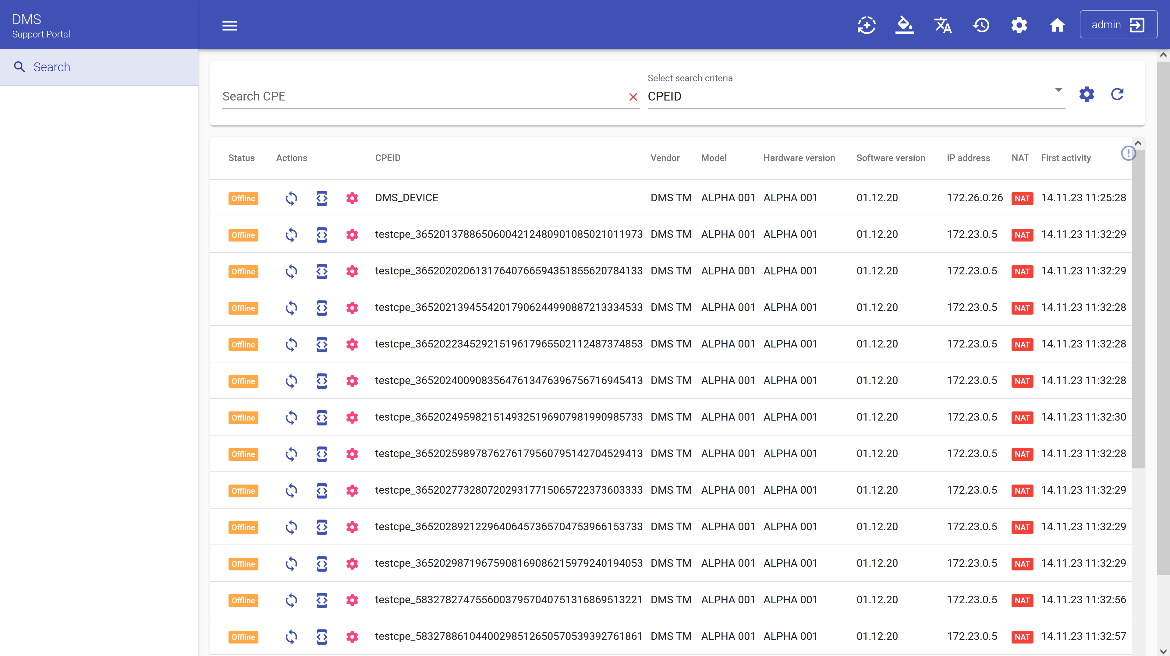
The "Status" field displays the device's state in relation to DMS. It does not reflect the device's status within your network.
Status options explain
| Status | Explain |
|---|---|
 | Information received |
 | New cpe in database |
 | Updating firmware |
 | CPE is rebooting |
 | Waiting for CPE session. CPE is unreachable |
 | Unsuccessfully authenticated request |
 | CPE interaction error |
 | Sending connection request |
 | CPE initialization |
The "Nat" column indicates whether Nat was detected during the device session in DMS.
Actions
In this table, there are three action buttons for each record:
- Send CNR test: Clicking on this button will initiate the "Connection Request" mechanism described in 3.2.2 TR-069. The results of this mechanism will be displayed as a message at the bottom of the page and may also change the device's status in the table.

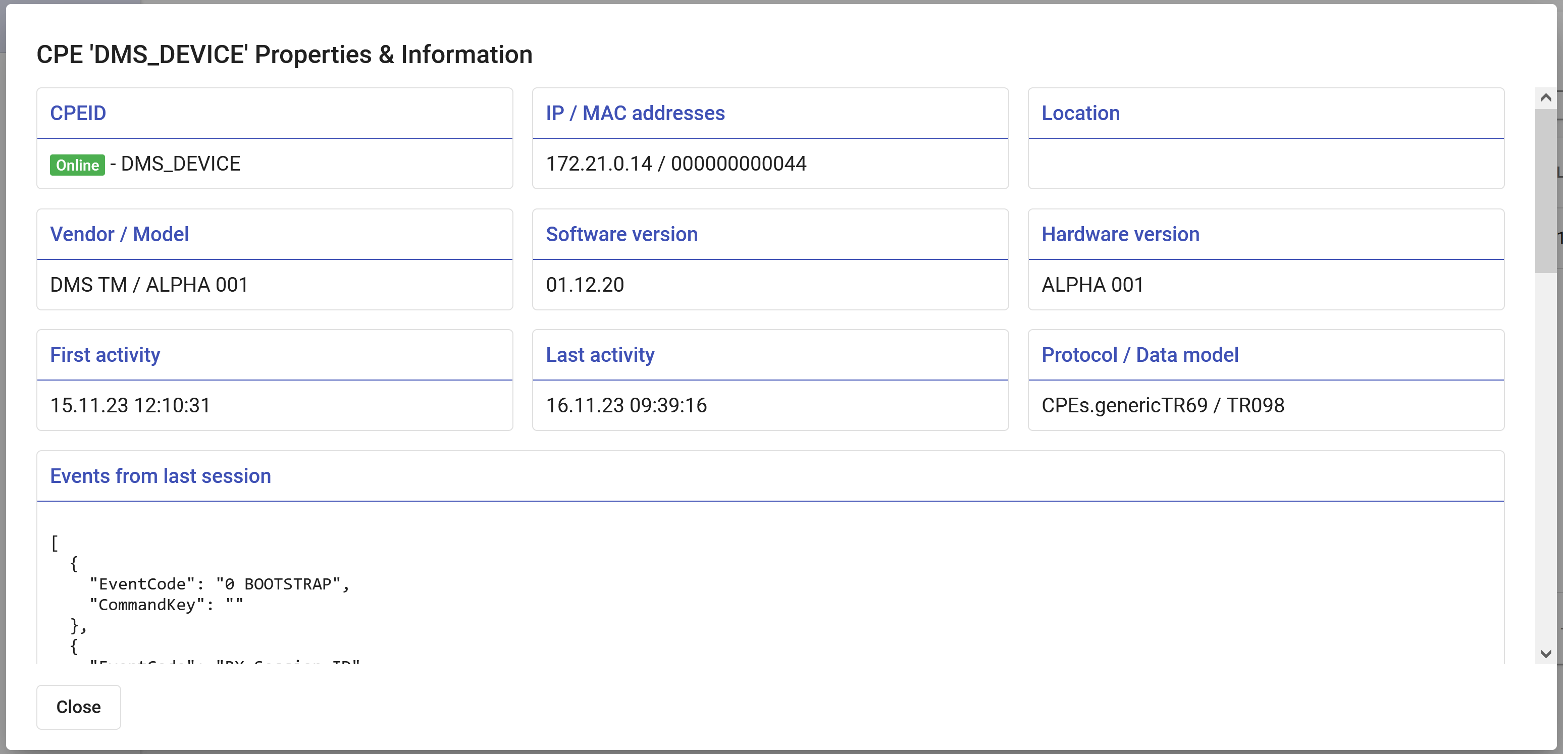
- Show CPE properties: This button opens the "Properties & Information" dialog box, containing information corresponding to the complete record in the "CPEStorage" table.
- Manage CPE: This is the most important action button that opens the complete "device card," which is automatically assembled based on the parameters available on your device.
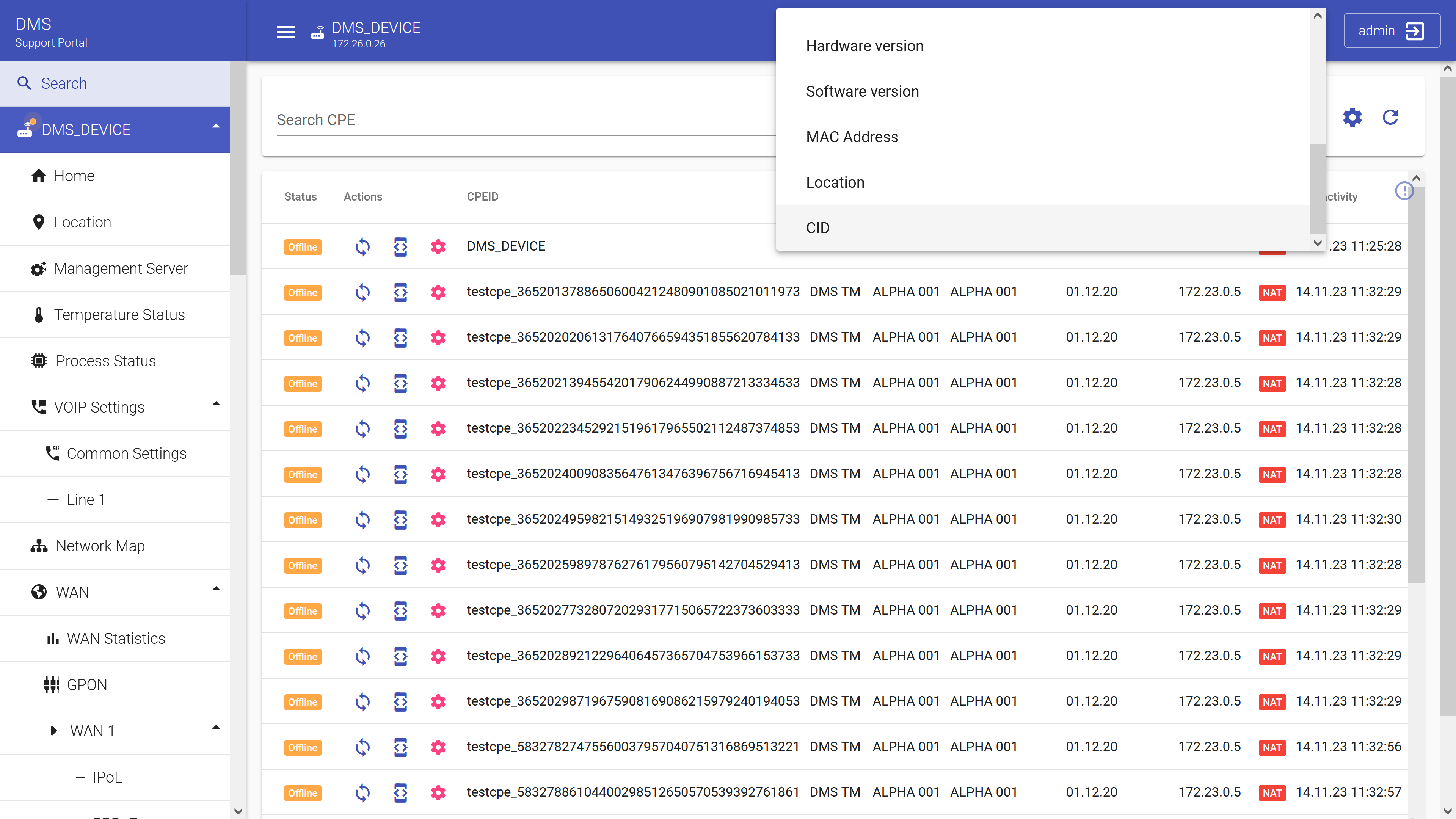
Search
The search in the table functions according to the description in this section.
The available search parameters and their descriptions
| Parameter | Meaning |
|---|---|
| "Status" | Displays for each device whether it is “up and running” ("Online") or not ("Offline") |
| "CPEID" | Identification number consisting of numeral or string of numerals that assigned to CPE device and used for its identification |
| "Vendor" | Company that manufactured CPE device |
| "Model" | Alphanumeric index that designates a set of device characteristics |
| "Hardware version" | "Hardware Version" is used to identify the type of hardware on which software is running. It can be used to differentiate different device types being tracked in the same project and different board revisions of the same device type |
| "Software version" | Assigned symbolic designation of software product in the form of numbers or letters |
| "IP Address" | Unique numeric identifier of a specific device in a computer network based on the TCP/IP protocol |
| "Protocol" | A network protocol is an established set of rules that determine how data is transmitted between different devices in the same network |
| "First Activity" | Timestamp of the first interaction between server and CPE device |
| "Last Activity" | Timestamp of the last interaction between server and CPE device |
| "Actions" | Activity taken by the user on the server for achievement a specific objective |
Device card
The device card is an automatically generated set of widgets that allow you to control the device. The composition of these widgets may vary from device to device, depending on the TR-069 parameters that the device has. Said parameters are constructed and translated into widgets based on the official Technical Reports TR-098 and TR-181.
In this section, the principles of operation of the most commonly encountered widgets will be described.
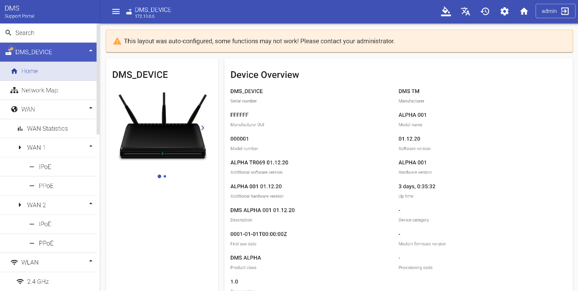
CPE Overview
Once you have selected the necessary CPE and clicked on the "Manage CPE" icon, you will see the table with information about this device. There will be displayed the image of the device and on the right side under the title "Device Overview" its main parameters. On the left side of the screen will be depicted the sections with configurations and diagnostic tests for this device. Select the desired settings or run the necessary diagnostic tests to continue.
Warning: The layout of the device represented in the table has been configured in automatic mode. Some functions may not work. Please contact your administrator for details.
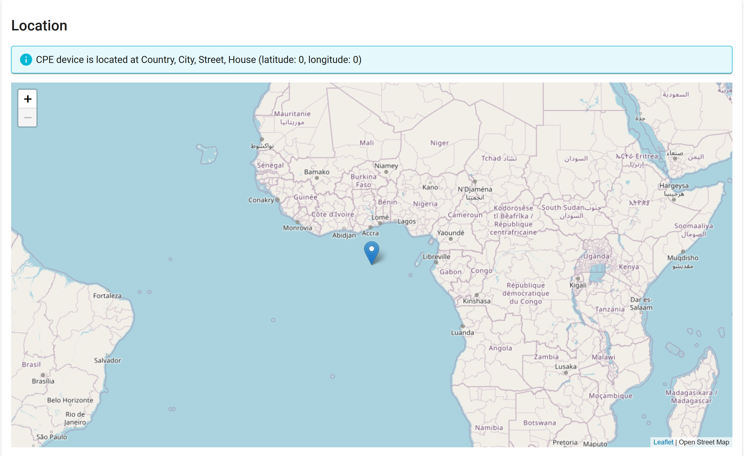
Location
This section is used to show location of CPE if it's "location" field is filled up properly. You can read about it in detail in Set Up Location chapter.
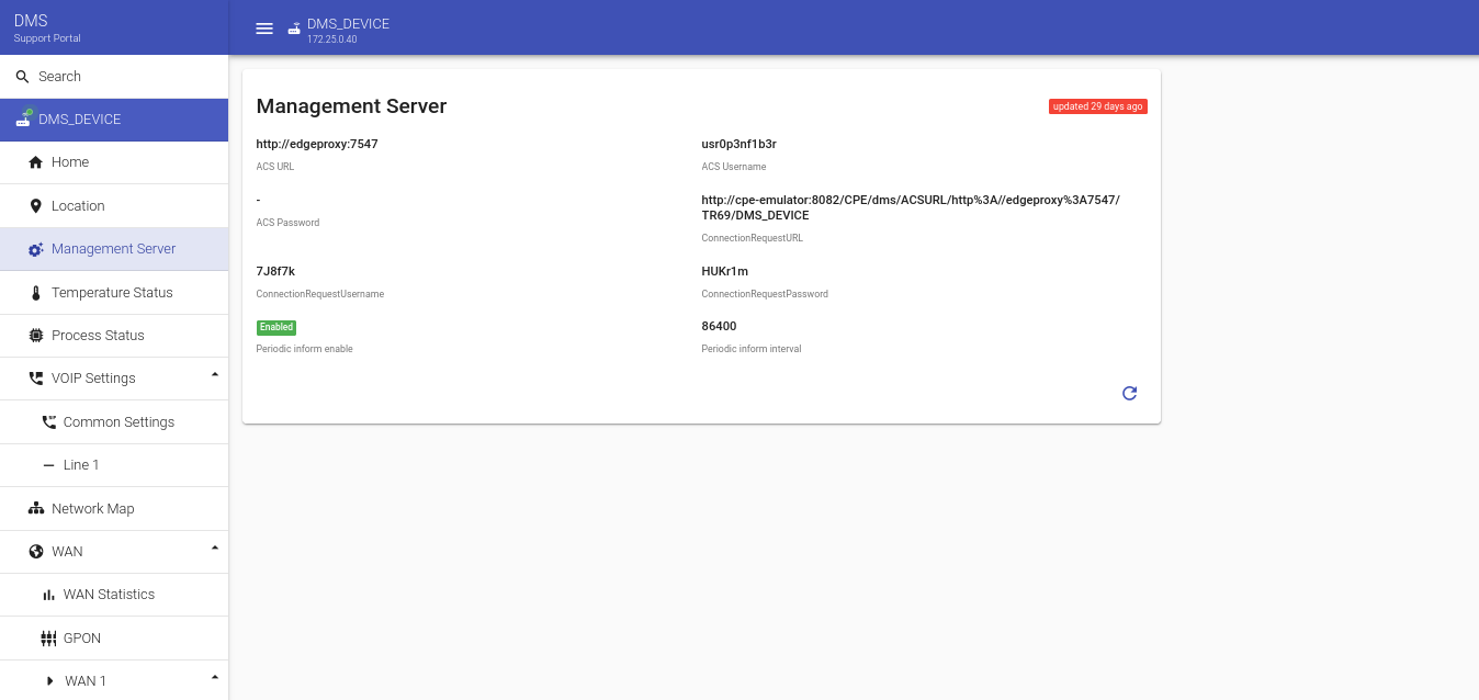
Management Server
This section displays the parameters of the Management Server that CPE is connected to. You can change these parameters in general CPE Overview screen, which can be accessed through Home button in the upper left corner, or by using NBI API.
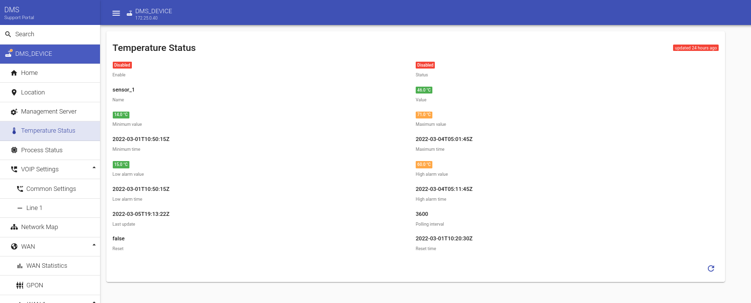
Temperature Status
If your device has working temperature sensor, temperature data of the CPE will be described in Temperature Status section. Parameters include maximal and minimal temperature, current temperature, undesired high and low "alarm values" and time of these alarms and temperature checks, as well as time interval for checking the temperature.
Process Status
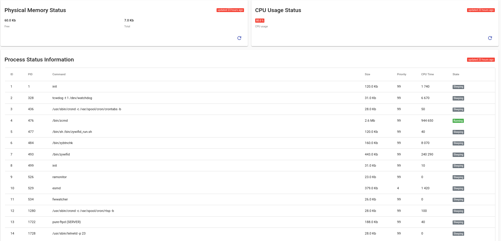
This section presents information about processes running on the CPE and memory and processor load on the CPE. This information can be used to diagnose performance degradation and find possible problems.
VOIP Settings
VOIP stands for Voice over Internet Protocol, which is a communications technology that allows users to interact by audio through an Internet connection, rather than through an analog connection. Voice-over-Internet Protocol converts the voice signal used in traditional phone technology into a digital signal that travels through the Internet instead of through analog telephone lines.
Common Settings
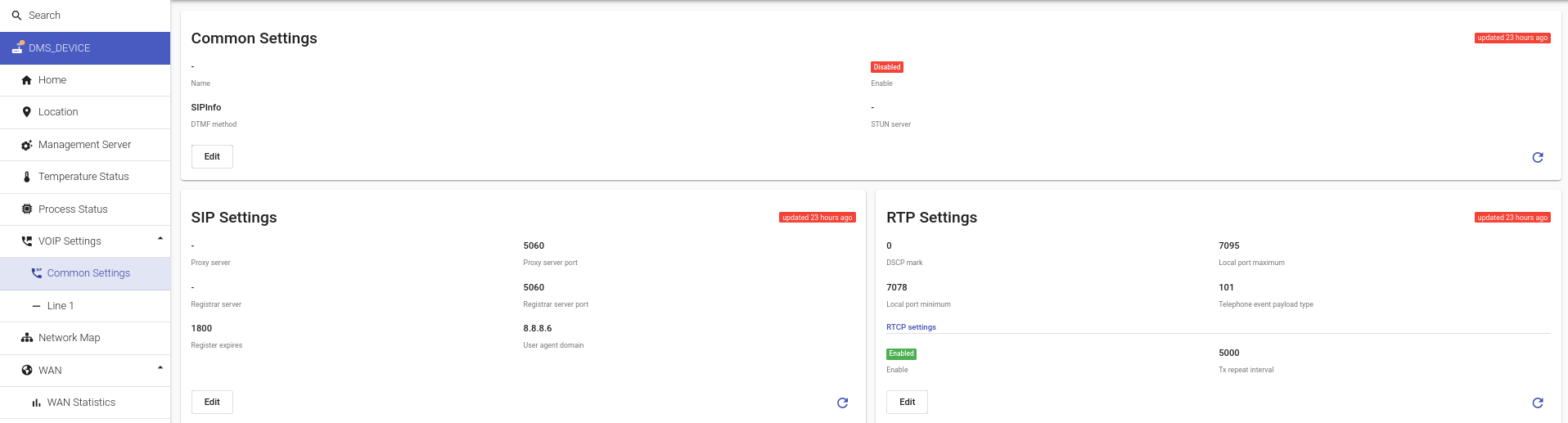
These are the general VoIP settings on the device, which includes SIP server settings, RTCP protocol settings (for sending debug logs of SIP calls) and DTMF and STUN settings for SIP.
For an emulated device there is one model example of pre-filled settings for a VoIP Line, however through your device specifications you can set up to 5 different lines.
Line 1
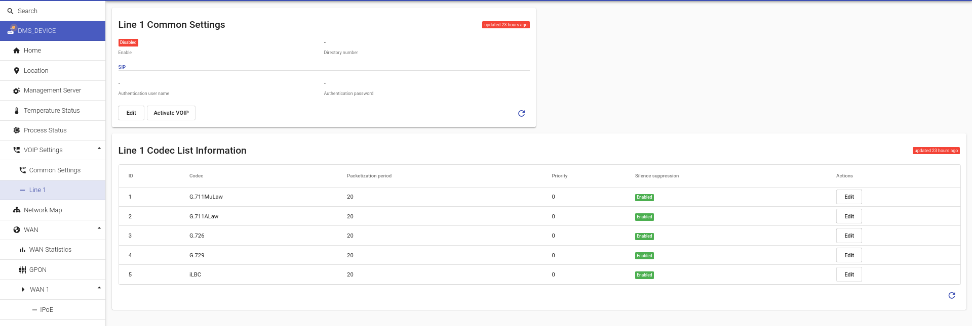
Line 1 (and further - according to the number of lines) includes VoIP line settings under the corresponding index, such as access details for this line (login-password) and a list of active codecs.
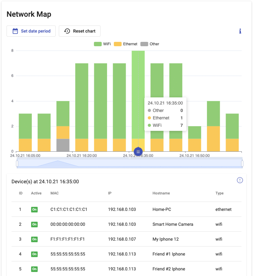
Network Map
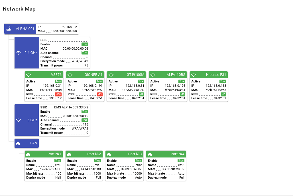
This part of the Support Portal displays all devices connected to the CPE, devices in active mode and those that were previously connected to the router but currently turned off, and which will be displayed in the Network Map for a certain period of time before updating the router.
DHCP
"DHCP" section identifies the settings of DHCP server on a CPE device. When it comes to making changes, you can set the required range of IP addresses, change subnet mask and IP interface addressing type and also enable or disable DHCP server.
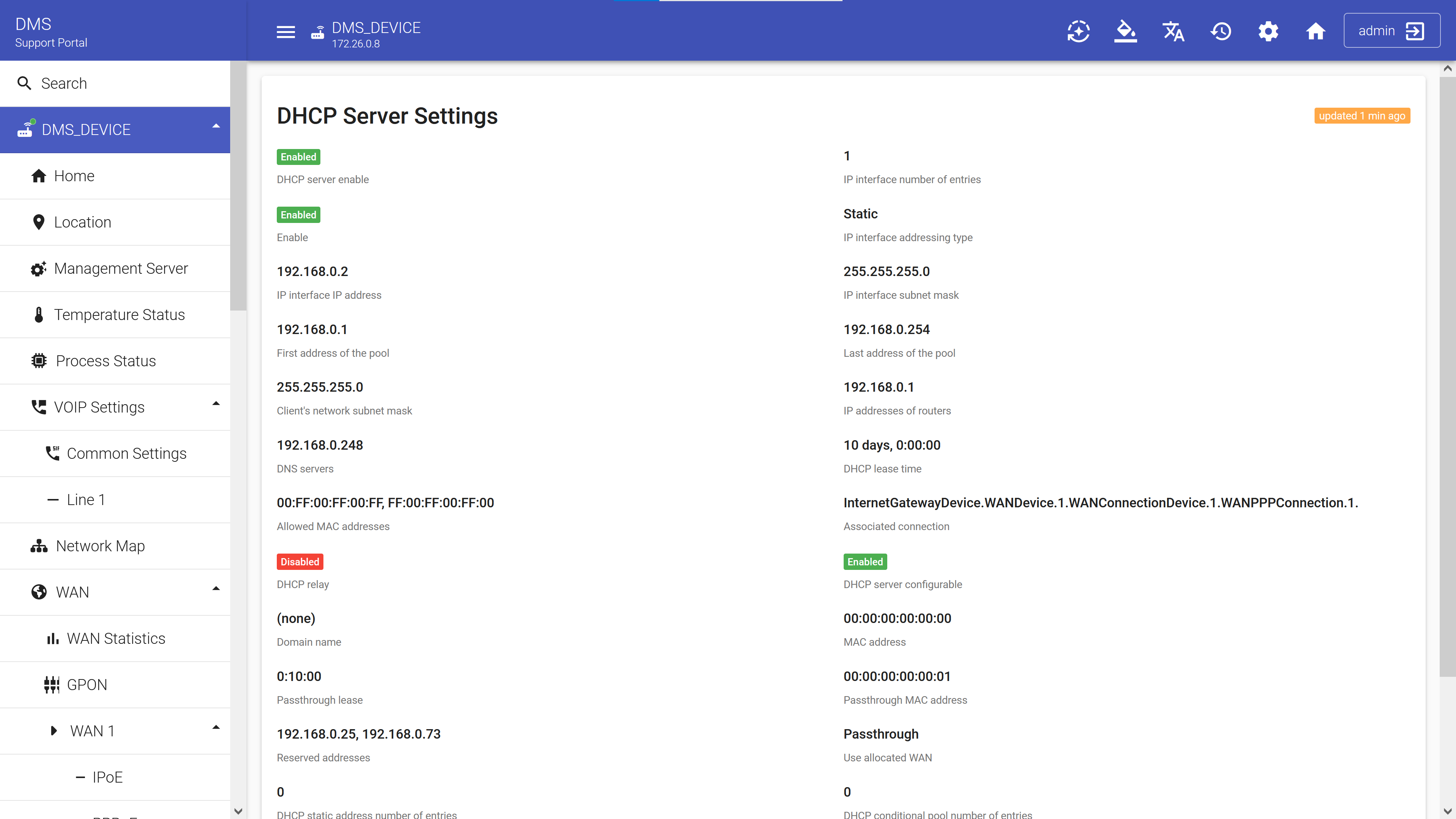
With the "Edit" button, that exists in each section of the Device Management Server where parameters can be changed, you can set all the desired settings.
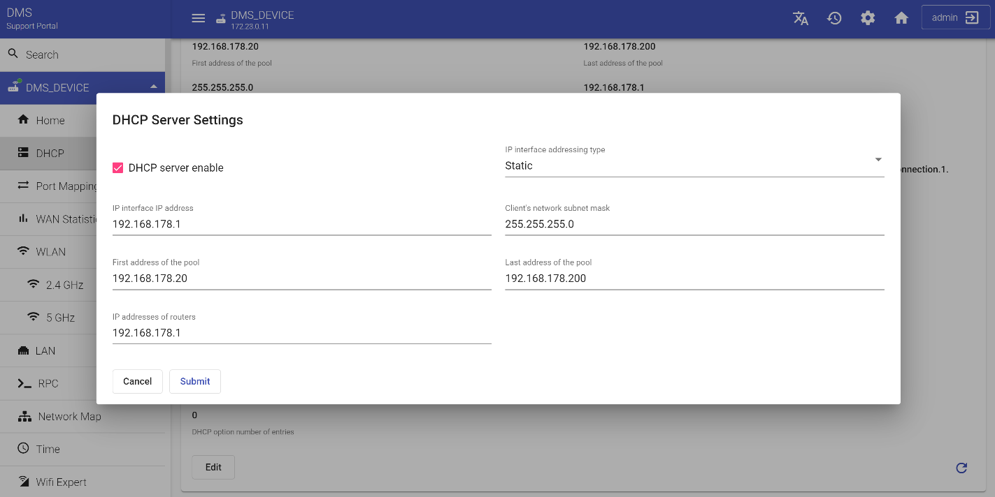
First of all, set "IP address of IP Interface" that represents the IP address of the LAN-side interface of the CPE device. Then designate "First and Last address of the pool" that specify the first and last address that will be assigned by DHCP server on the LAN interface. Change the subnet mask that defines a range of IP addresses available within a network and "IP addresses of routers" if necessary.
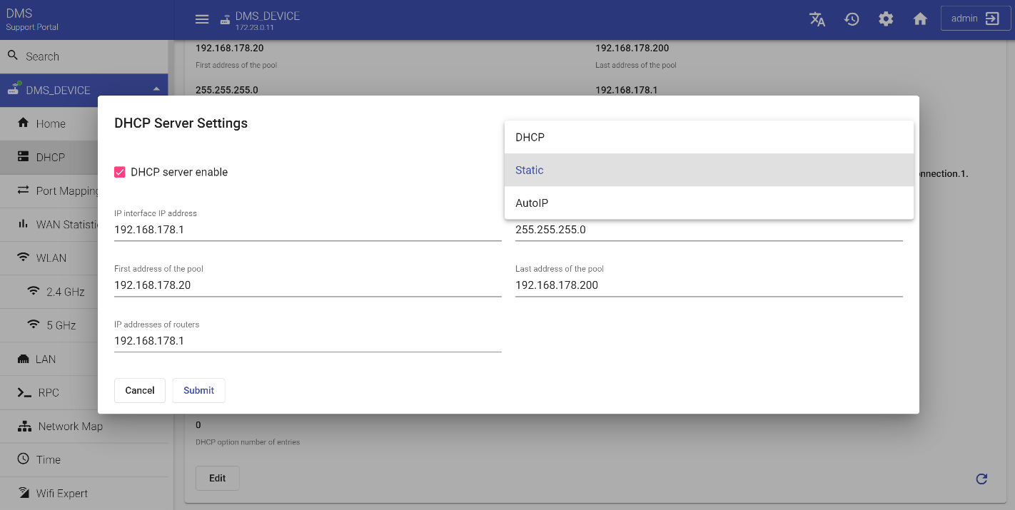
And finally, set "IP interface addressing type". It represents the addressing method used to assign the LAN-side IP address of the CPE on this interface. Select one of the variants:
- DHCP
- Static
- AutoIP
If you want to change configuration of DHCP server on the LAN interface, select true variable ![]() . If this variable is set to false, the CPE will restore its default DHCP server settings.
. If this variable is set to false, the CPE will restore its default DHCP server settings.
When all changes have been made press the "Submit" button.
Port mapping
You can make certain applications that run on a server in the internal network (for example, a Web or FTP server) be available from the external network. For that you can set in the router the mapping between the ports used by certain applications and the IP addresses of those virtual servers on the internal network on which these applications run. In this case we use "Port Mapping". When editing, you can select "Protocol", to set "IP address", external or internal port and add rules. This section contains all NAT port mappings associated with this connection, including static and dynamic port mappings programmatically created via local control protocol, such as UPnP.
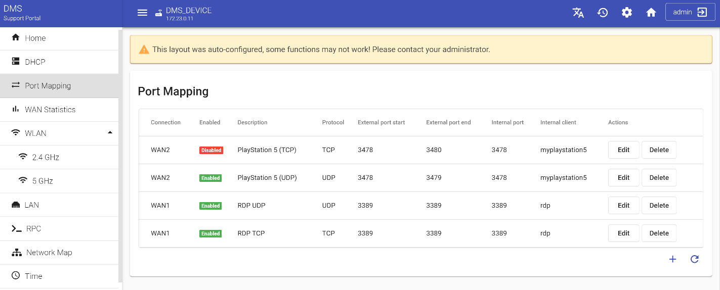
The first column Connection is a user-readable name of IP or PPP connection on the WAN interface of a CPE. All other columns are rules that can be applied to this connection. You can change them manually and set the required parameters. Click the "Edit" button.
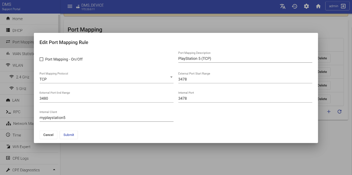
In the pop-up window select the required field. "Port Mapping Protocol" can be selected from two user-defined variables
- TCP
- UDP
Fill in the "Port Mapping Description" field. This is a user-readable description which can be freely chosen by you. Then indicate "External Port Start and End" range. The first digital value specifies the first port of a range of external ports that the NAT gateway would listen on for connection requests to a corresponding Internal Port. Inbound packets to this external port on the WAN interface will be forwarded to "Internal Client" on the "Internal Port". A value of zero (0) represents a "wildcard". If this value is a wildcard, connection requests on all external ports (that are not otherwise mapped) will be forwarded to "Internal Client". In the wildcard case, the value(s) of "Internal Port" on "Internal Client" are ignored.
When wildcard values are used for Remote Host and/or External Port, the following precedence order applies (with the highest precedence listed first)
- Explicit Remote Host, explicit External Port
- Explicit Remote Host, wildcard External Port
- Wild card Remote Host, explicit External Port
- Wild card Remote Host, wildcard External Port
If an incoming packet matches the criteria associated with more than one entry in this table, the CPE must apply the port mapping associated with the highest precedence entry. External Port End Range indicates the last port of the external port range that starts with External Port. If an external port range is specified, then the behavior described for External Port applies to all ports within the range. A value of zero (0) indicates that no external port range is specified, i.e. that the range consists only of External Port. If External Port is zero (wildcard), the value of this parameter must be ignored. If specified, the value of this parameter must be greater than or equal to the value of External Port.
After the above operations indicate Internal Port and Internal Client. Internal Port is a port on Internal Client that the gateway should forward connection requests to. A value of zero (0) is not allowed. Internal Client is an IP address or DNS host name of the client on the LAN. Support for an IP address is mandatory. If an Internal Client is specified as an IP address and the LAN device's IP address subsequently changes, the port mapping must remain associated with the original IP address.
Support for DNS host names is optional. If Internal Client is specified as a DNS host name and the LAN device's IP address subsequently changes, the port mapping must remain associated with this LAN device. In this case, it is the responsibility of the CPE device to maintain the name-to-address mapping in the event of IP address changes. Read access to this parameter must always return the exact value that was last set by the ACS. For example, if the internal client is set to a DNS host name, it must be read back as a DNS host name and not as an IP address. You can’t leave the empty string in the Internal Client field. In this case, the Internal Client will be considered unconfigured. If this parameter is unconfigured, this port mapping must not be operational.
After all manipulations activate "Port mapping On" ![]() function in the dialog box. Initially it is disabled by default. Then click the "Submit" button. The process of Port Mapping configuration can be considered complete.
function in the dialog box. Initially it is disabled by default. Then click the "Submit" button. The process of Port Mapping configuration can be considered complete.
Time
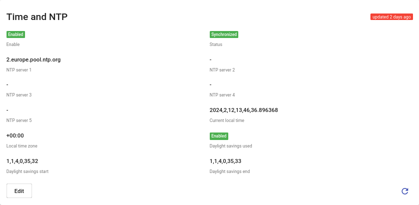
Time synchronization is quite an important thing. Without accurate time, update services, some CPE devices, messengers, and some smart home applications will not work. Setting the time and configuring synchronization on the device is not difficult, but it requires strict adherence to the instructions. When you press the "Time" configuration button on the dashboard, you will see a table containing the following information: Status of synchronization, Local time zone identification, list of NTP Time servers, Start and End of daylight savings.
If you want to edit this information, click on the "Edit" key, then make the necessary alterations in the appeared dialog window.

Set NTP server parameters, either representing a host name or IP address, and select "Local time zone name" from the list of suggested options.
Remember to set Enable to true to activate the settings. If you set this parameter to false, the CPE device will restore its default settings. Then click the "Submit" button to send the form data.
WAN
WAN Statistics
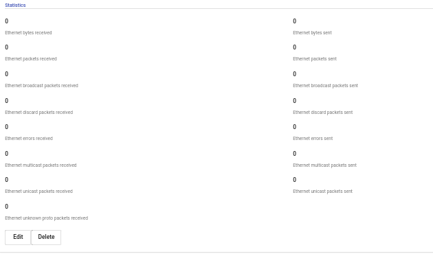
This tab shows all the necessary statistics and data related to broadband networks (WAN). WAN network is developed for communication between geographically distant devices, for connection to external resources and services and remote users. WAN networks are often used to carry different types of traffic: voice, data, and video. Although these statistics are not changeable, they indicate the parameters of all connections in the network. This allows the operator to control the stable functioning of all devices inside of it.
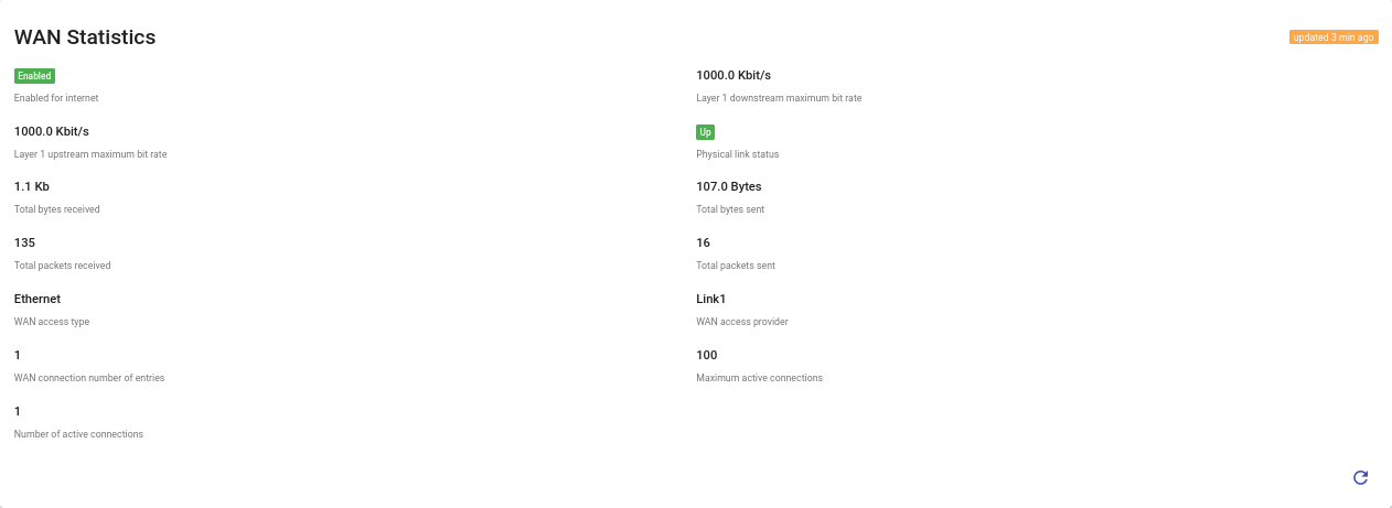
The data provided in this table include the Layer 1 upstream and downstream maximum bit rate. These fields specify the maximum downstream and upstream theoretical bit rate for the WAN device in bits per second. It describes the maximum possible rate given the type of interface assuming the best-case operating environment, regardless of the current operating rate. For example, if the physical interface is 100BaseT, this value would be 100000000, regardless of the current operating rate. You can also analyze the total number of bytes that were received or sent. These are the counters for the total number of bytes received downstream or sent upstream across all connection service instances on the WAN device. Data concerning the total number of sent and received packets is also available for your consideration. Maximum active connections indicate the maximum number of active connections the CPE can simultaneously support. Number of active connections show the number of WAN connection service instances currently active on this WAN interface.
The type of WAN access specifies the WAN access technologies that use modem for transferring and receiving data. The possible options are DSL, Ethernet, POTS. The other information with regard to WAN network will include the name of provider of WAN access and number of entries and active connections. "Enabled for internet" button is used to enable or disable access to and from the Internet across all connection instances.
GPON
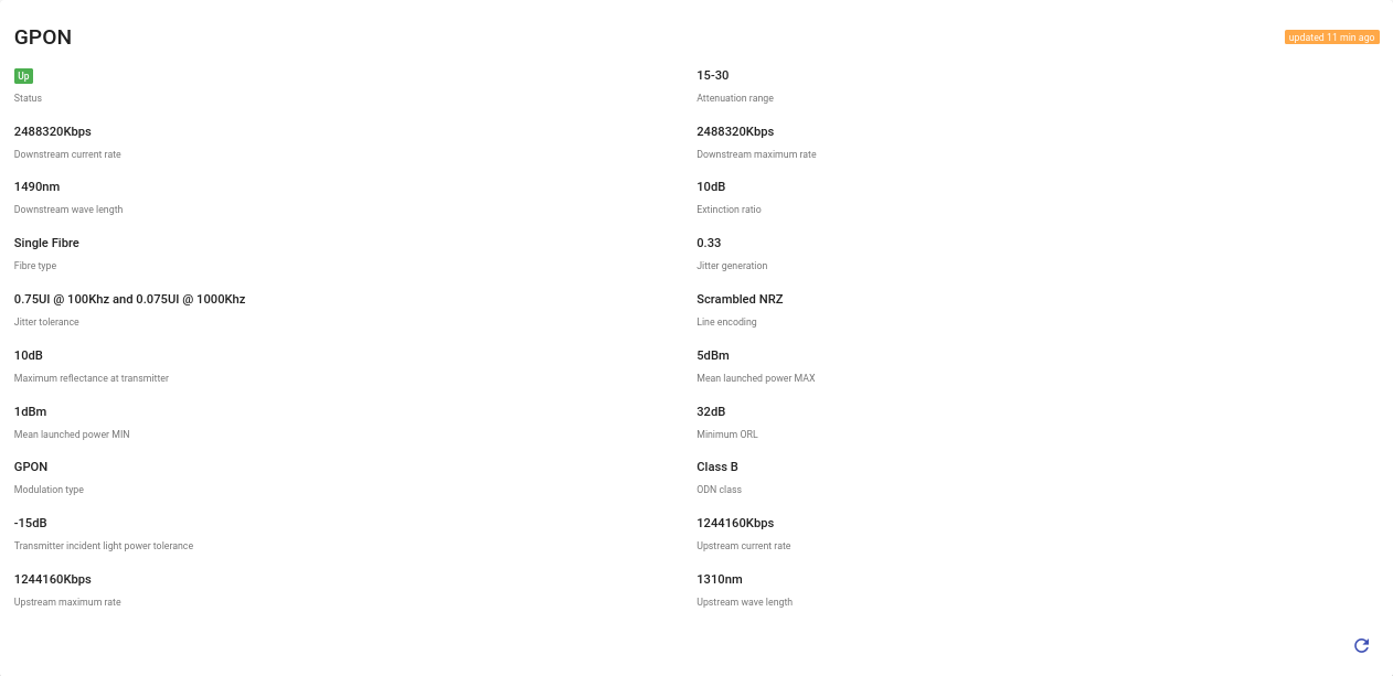
GPON stands for Gigabit Passive Optical Network; this widget displays the status of the physical and link layers of the GPON connection such as the received and transmitted power of the optical module, the agreed bitrate, modulation types, etc. The appearance of this section may vary depending on the features of the device as this parameter is custom and is not specified explicitly by official technical reports.
WAN 1 / WAN 2 (IPoE, PPPoE)
IPoE protocol
In order to provide a common connection, you can use two types of protocols: IPoE and PPPoE.
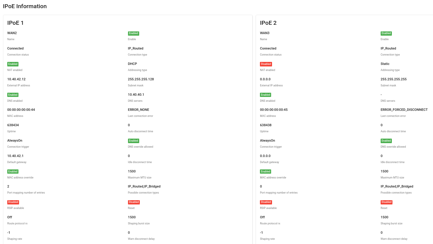
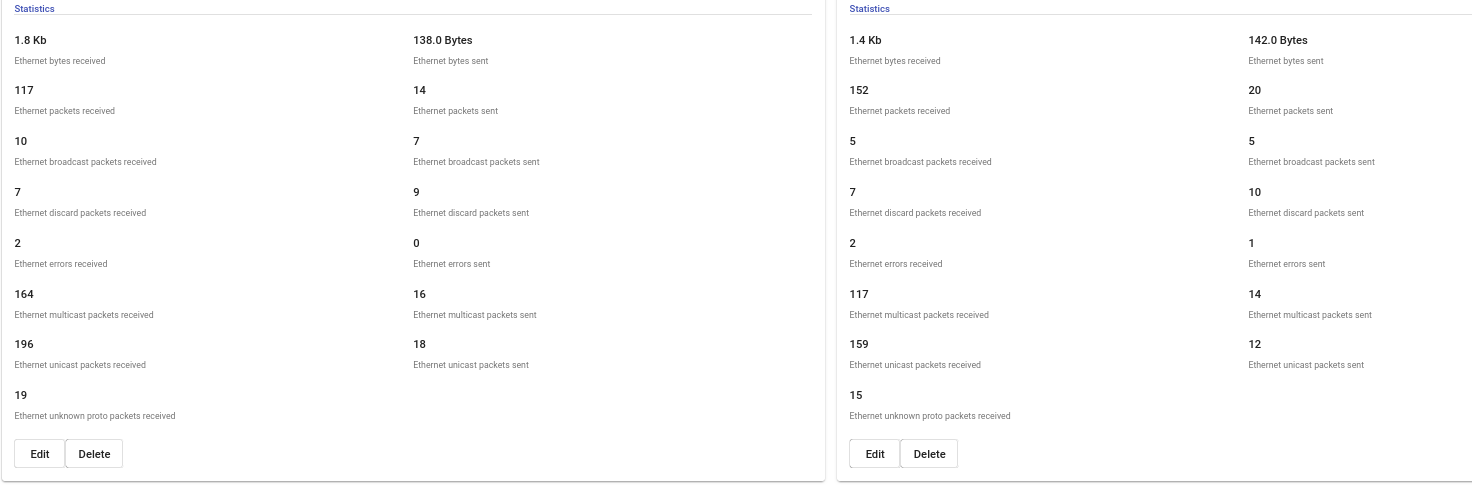
With IPoE, the user doesn’t need to enter a login and password when connecting to the Internet: the DHCP server will dynamically assign an IP address and other relevant configuration information to the network device. The IP and MAC information is then automatically registered. This saves limited IP address space. With IPoE, the information flows do not contain coded information, so they are processed much faster. IPoE allows subscribers to roam anywhere in the network and automatically obtain an IP address when they reconnect. With this technology, you can connect all the devices in your home to the Internet: TVs, game consoles, smartphones, etc. As can be seen in the IPoE Information table, you can get relevant data about the "Connection Type" and "Connection Status", "IP and MAC Address", "IP address of DNS server", statistical information about the number of packets sent or received, total number of bytes, etc.
The most important information can be changed or updated. Click the "Edit" button to make the necessary changes in the dialog box.
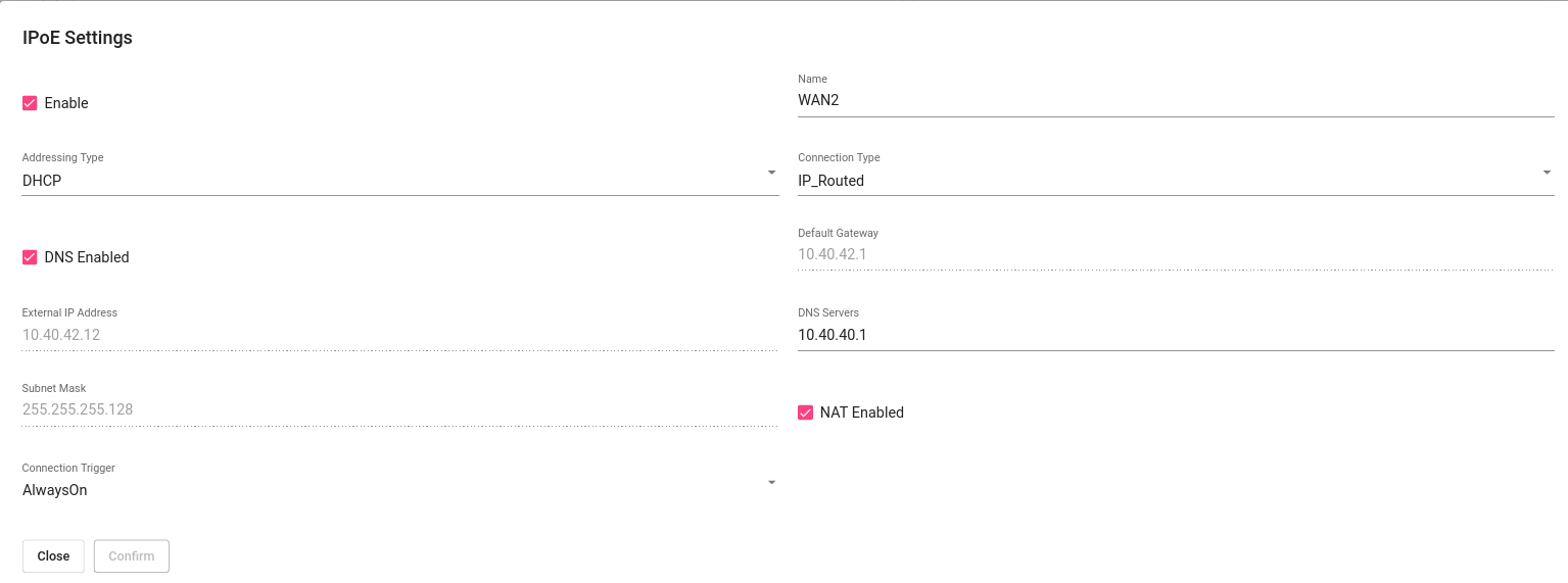
You can set the "Type of connection", "IP address of DNS server" and "Addressing type" at your discretion. If you select Static position in the "Addressing type" line, you can also set "External IP address", "Subnet mask" or "Default gateway" parameters. Make sure that the checkboxes "NAT enabled", which indicates that Network Address Translation (NAT) is enabled for this connection, and "DNS enabled", which specifies whether the device should try to query a DNS server over this connection are enabled. Then click "Submit" button.
PPPoE protocol
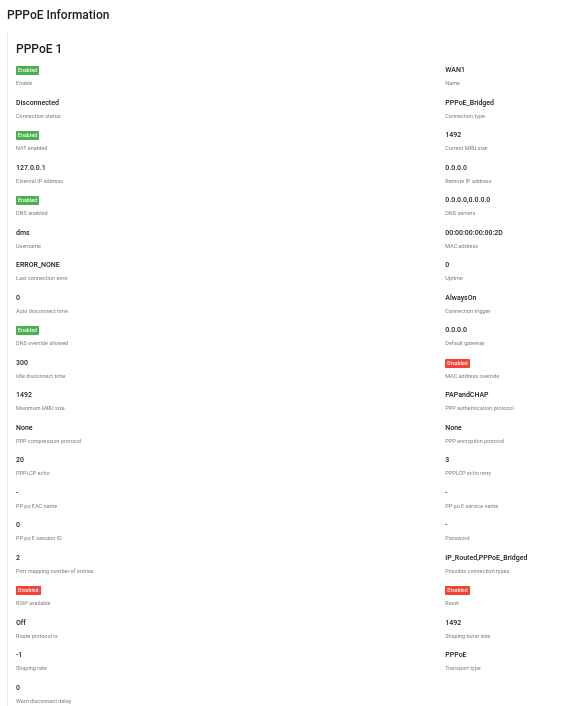
PPPoE is an acronym for Point-to-Point Protocol over Ethernet, which stands for Point-to-Point Network Data Transfer Protocol. In other words, PPPoE is a "tunnel" created in a virtual network between a pair of points. The first point is the service provider's server and the second point is any end-user CPE device connected to the Internet. The connection between points is established using routers, modems, repeaters or other devices with Ethernet ports. The protocol uses the functions of user authorization and traffic compression and encryption. All necessary information about the PPPoE connection is collected and can be analyzed in this table.
You can define "Status and Type of Connection", "External IP or MAC Address", "Last Connection Error", "Current MRU Size", etc. Click the "Edit" button if you want to set or change any parameter.
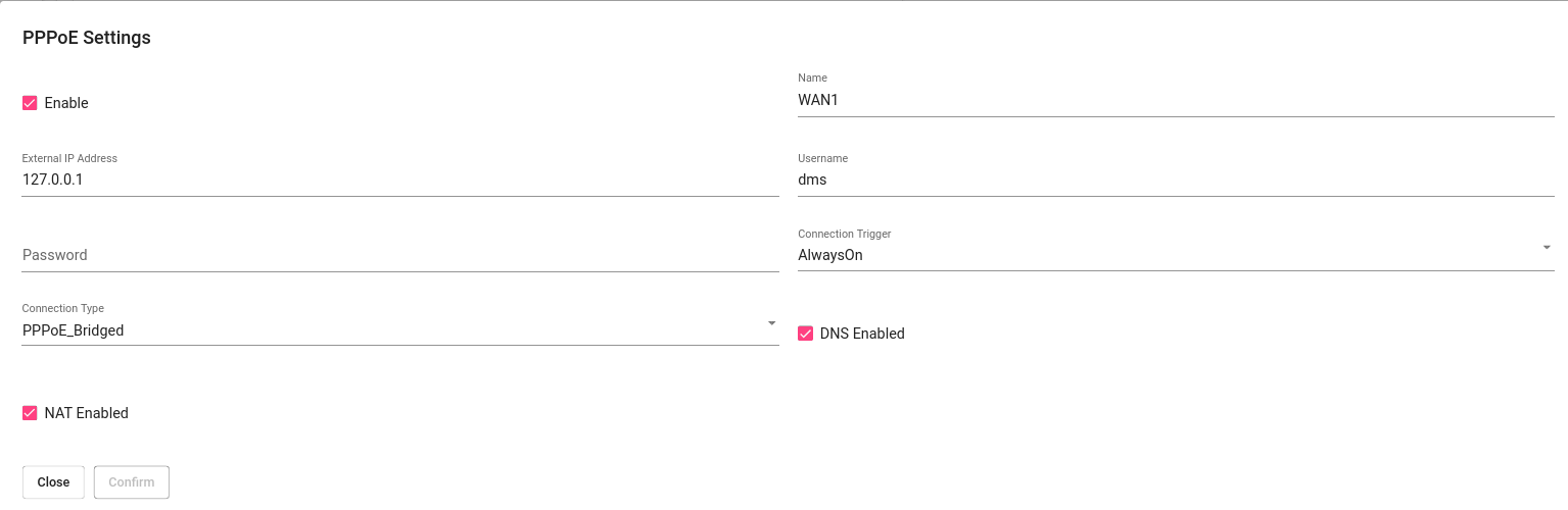
In the dialog box, you can set the "User Name" and "Password", specify the "External IP address" or "Connection Trigger" to be used to establish the PPP connection. Make sure you also select "Connection Type" and activate the "DNS enabled" and "NAT enabled" checkboxes, then click "Submit" to apply the changes.
VLAN Config
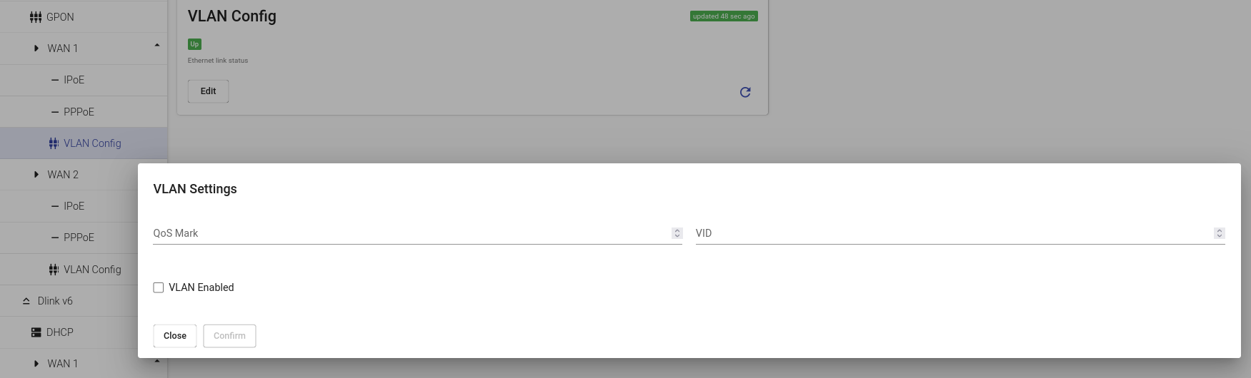
VLAN is a custom network which is created from one or more local area networks. It enables a group of devices available in multiple networks to be combined into one logical network. The result becomes a virtual LAN that is administered like a physical LAN. The full form of VLAN is defined as Virtual Local Area Network. In the VLAN section you can enable VLAN, set QoS Mark and VLAN-ID (VID) to configure your network. For specific examples see the VLAN Section of Technical Report.
WLAN
If you click on the tab "WLAN", you will see the information with a list of all available WLAN interfaces. This section is editable, so you can easily set the parameters you need. Here is a detailed review.
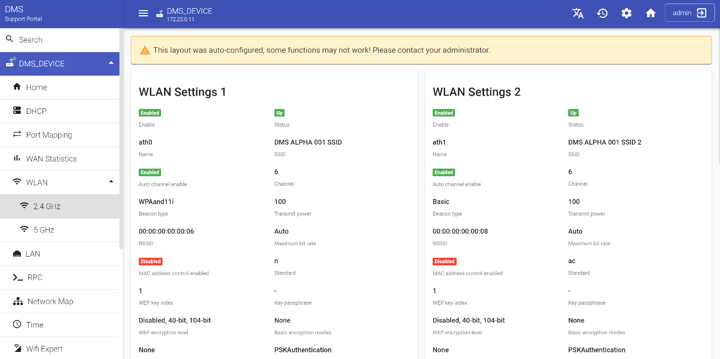
First, select the frequency range. Available options are 2.4 and 5 GHz. Then click the "Edit" button in any WLAN Settings section that you need.
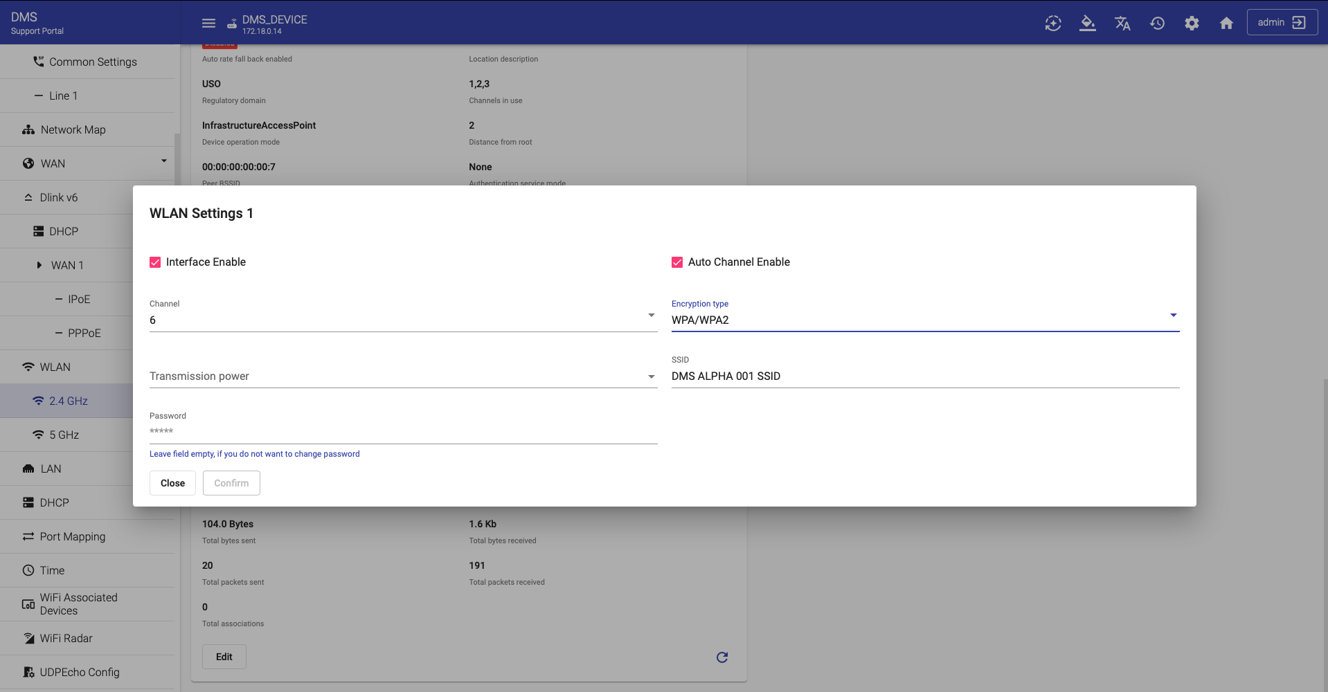
In the appeared dialog window indicate the "SSID" field. The "SSID" is an identifier that is attached to packets sent over the wireless LAN that functions as a "password" for joining a particular radio network (BSS). Note: If an access point wishes to be known by more than one SSID, it must provide a WLANConfiguration instance for each "SSID". Select channel.
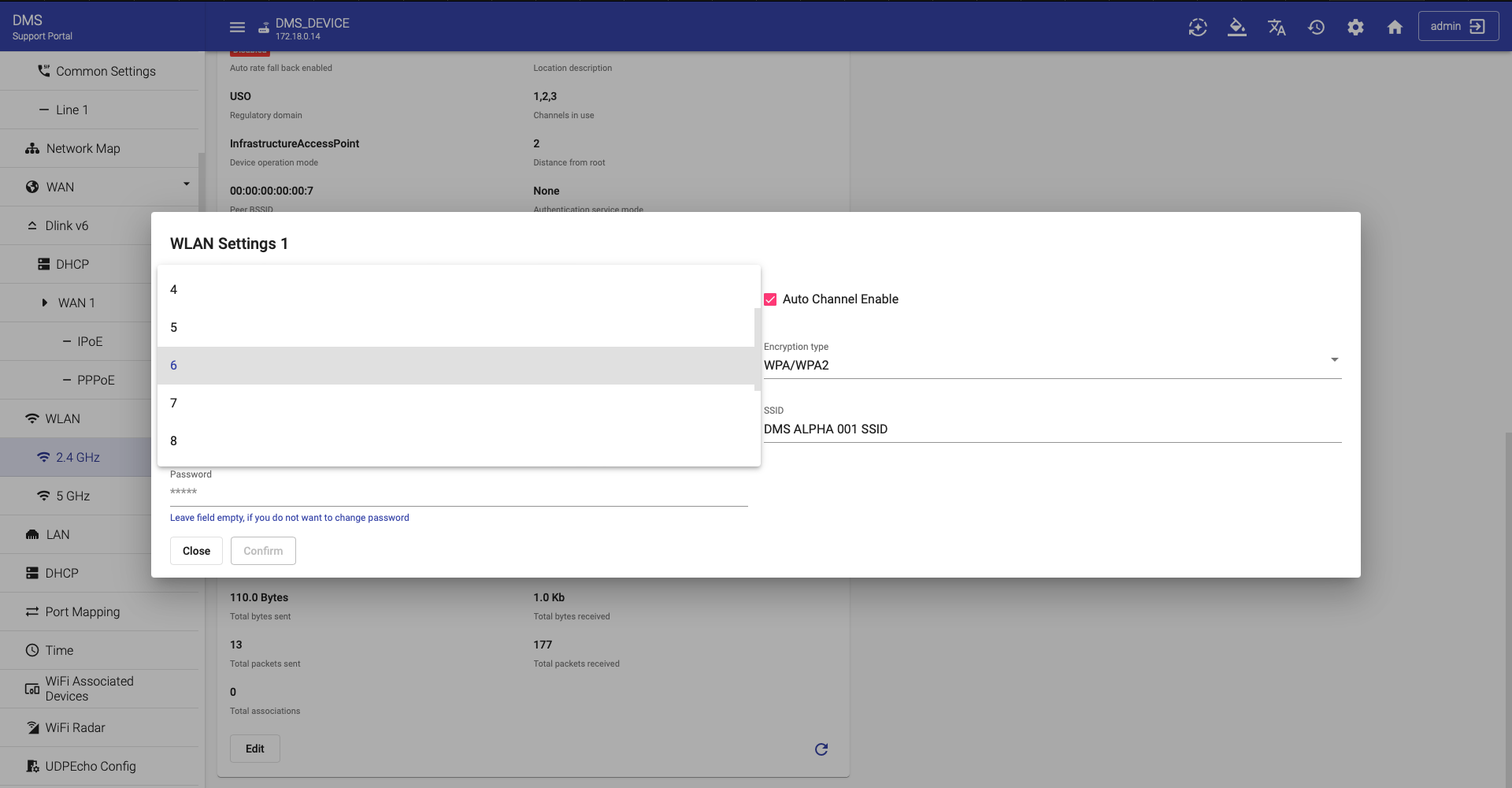
This is the current radio channel used by the connection. To request automatic channel selection, set Auto channel enable to true ![]() . Whenever Auto channel enable is true, the value of the Channel parameter must be the channel selected by the automatic channel selection procedure. The same way select "Transmit power", then define the "Encryption type".
. Whenever Auto channel enable is true, the value of the Channel parameter must be the channel selected by the automatic channel selection procedure. The same way select "Transmit power", then define the "Encryption type".
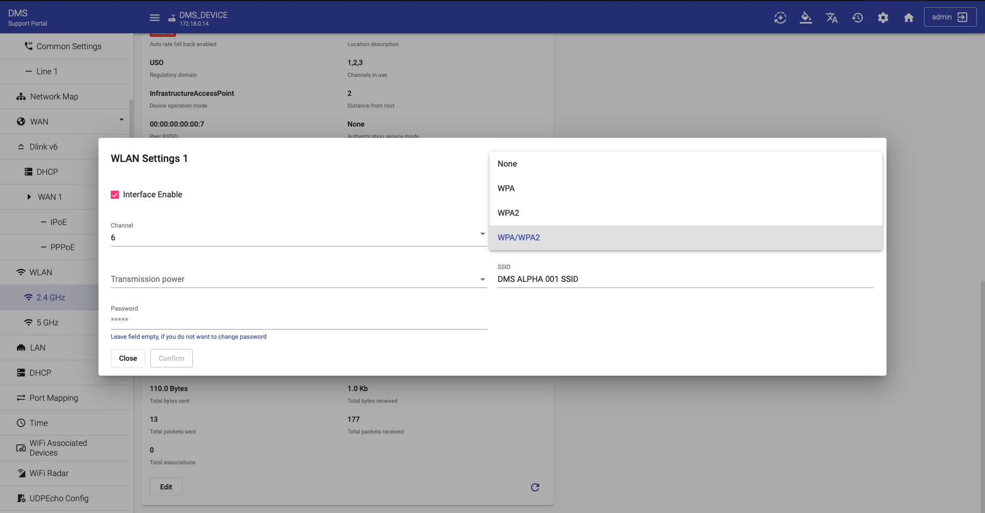
A "None" value means that no capabilities are currently enabled on the access point and that no stations will be able to associate with it. Enumeration of:
- None
- WPA
- WPA2
- WPA/WPA2
Set desirable Key passphrase, set SSID enable to true ![]() and then click the "Submit" button. Repeat the same steps in the other WLAN Settings section if necessary.
and then click the "Submit" button. Repeat the same steps in the other WLAN Settings section if necessary.
LAN
This part of Device Management Server displays existing LAN interfaces their status and state. As is the case with the previous sections, the changes can also be made by a technical specialist throughout the dialog window that you will see by clicking the "Edit" button.
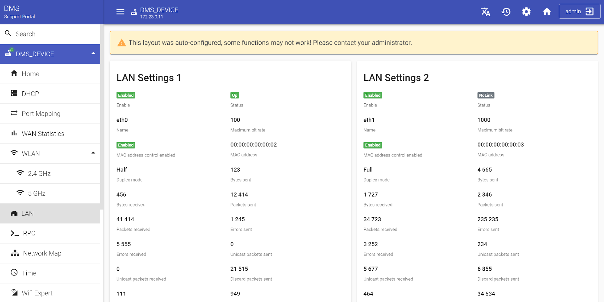
The currently editable fields include "Maximum bit rate" and "Duplex mode".
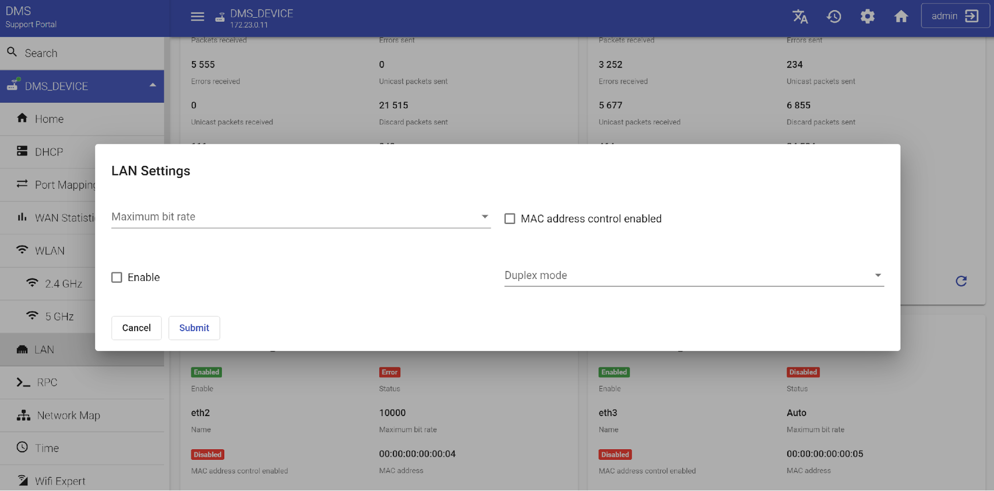
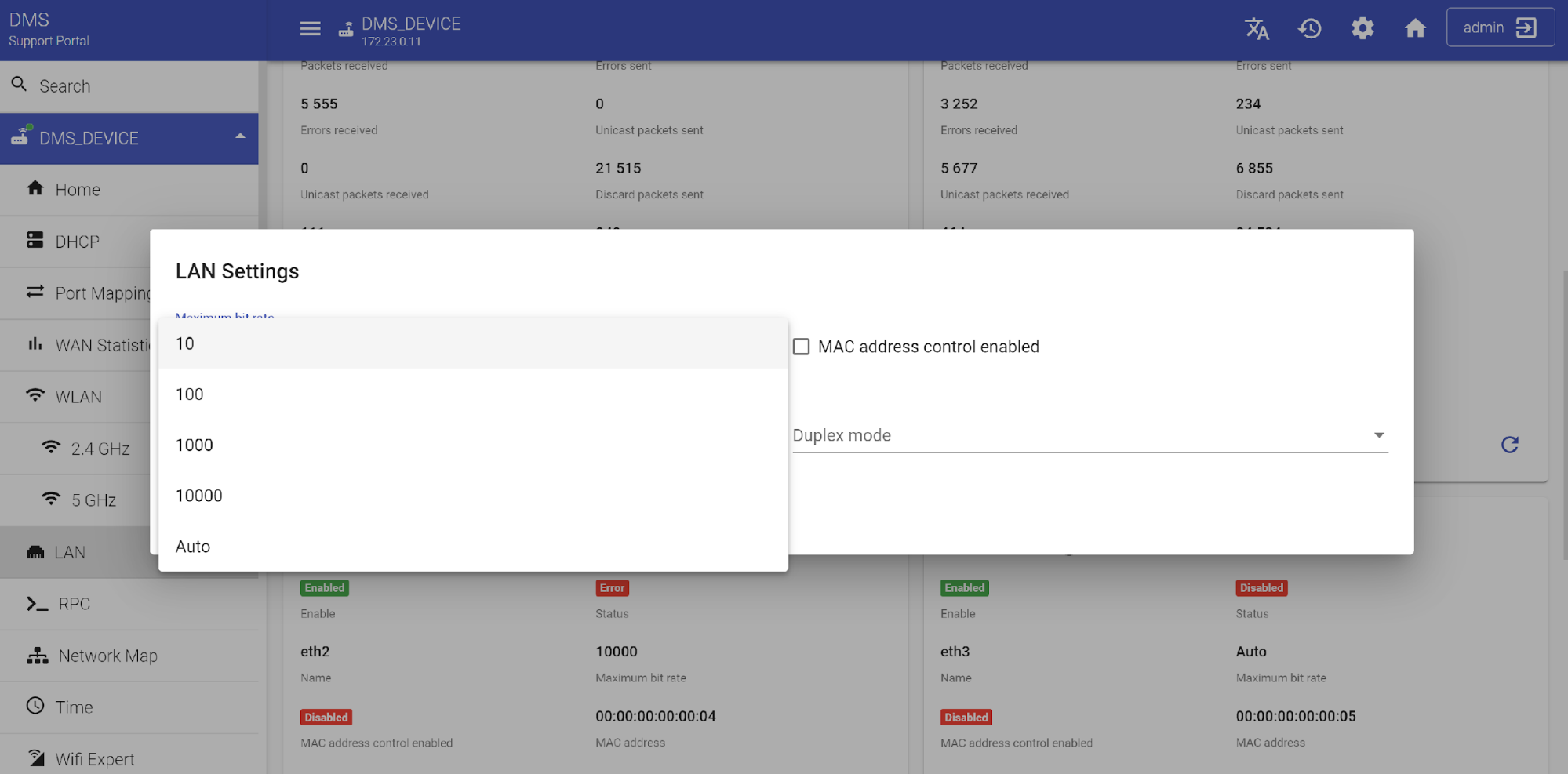
"Maximum bit rate" is the maximum upstream and downstream bit rate available to this connection. Select the values from:
- 10
- 100
- 1000
- 10000
- Auto
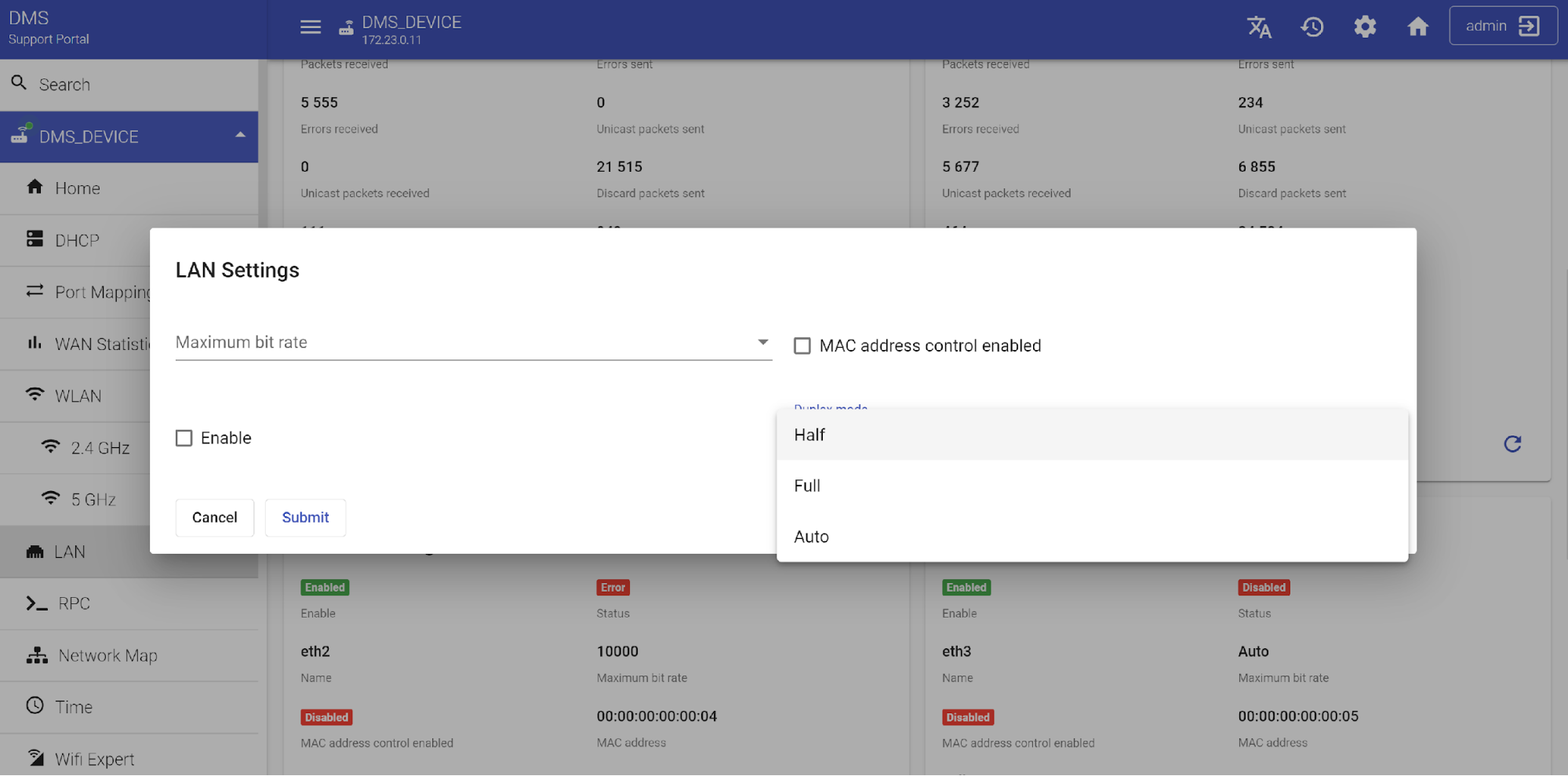
"Duplex mode" is the packet transfer method. Select the necessary value. In Half duplex mode, the signal is sent in both directions, but one at a time. In Full duplex mode, the signal is sent in both directions at the same time. In Auto mode, the device itself decides on the method of sending.
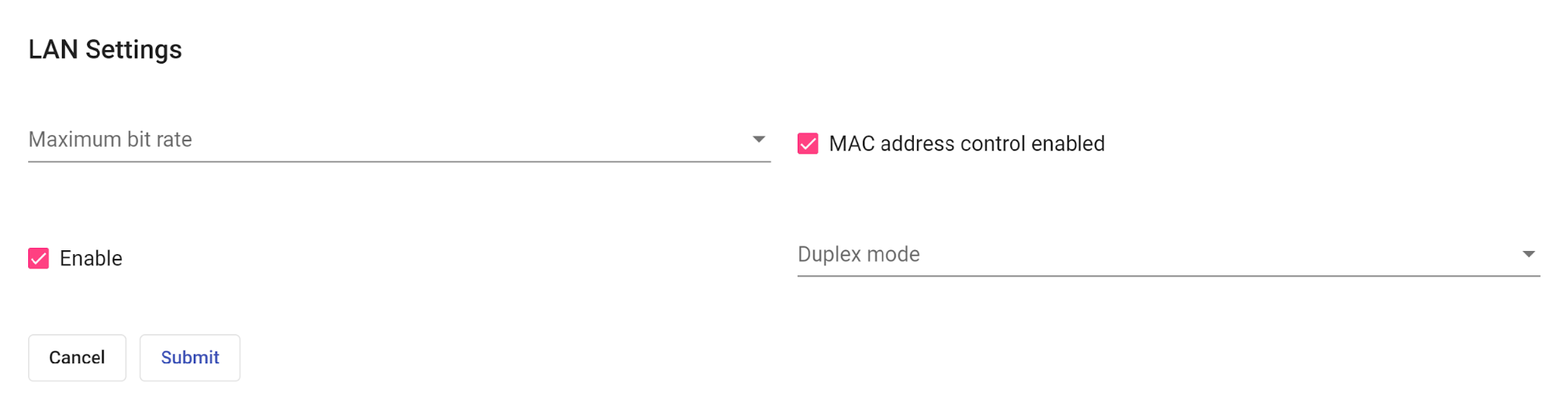
After choosing the appropriate parameters, do not forget to set "MAC address control enabled" and "Duplex mode enable" to true ![]() and then press the "Submit" button. The Lan setting procedure is now complete.
and then press the "Submit" button. The Lan setting procedure is now complete.
RPC
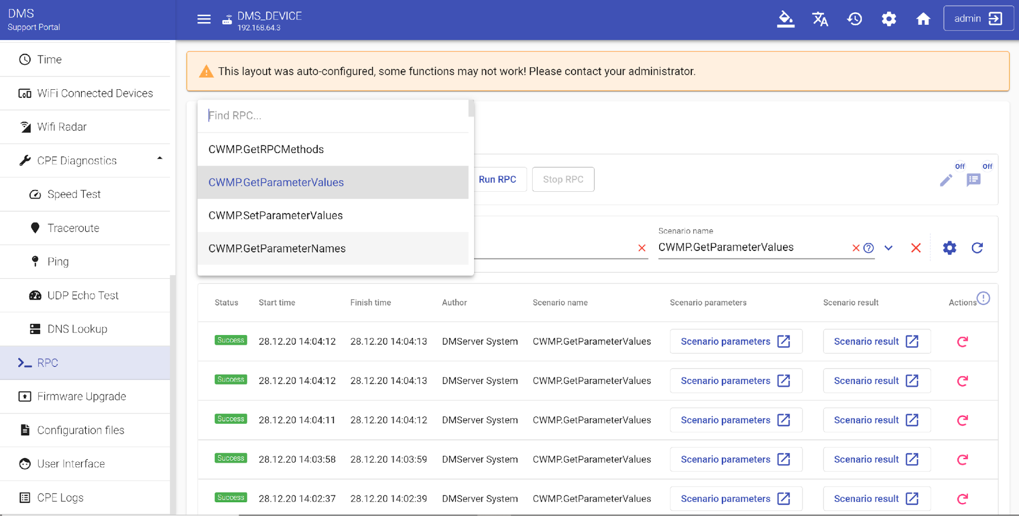
Remote Procedure Call (RPC) is a method of inter-process communication or model of network programming. It is used for point-to-point communication between software applications. (e.g. CPE and ACS). RPC mechanisms are used when a computer program calls the execution of a procedure or subroutine in another address space, which is coded as a normal procedure call. In "RPC" section of our Device Management Server, you can select the required RPC scenario, then run it and get the result. The available RPCs include "GetRPCMethods", "GetParameterValues", "SetParameterValues", "GetParameterNames", "GetParameterAttributes", "SetParameterAttributes", "CWMP.AddObject", "CWMP.DeleteObject", "CWMP.Reboot", "CWMP.Download" and others (see drop down menu for details). Here's an example of the process of applying parameters using the "GetParameterValues" argument. This argument returns an array of string objects containing all the values the given request parameter has. Select the required RPC method (in our case "GetParameterValues") and press "Run RPC" button.
A confirmation window will appear asking if you really want to start execution of RPC task. Verify method and parameters value then press "Start" button.
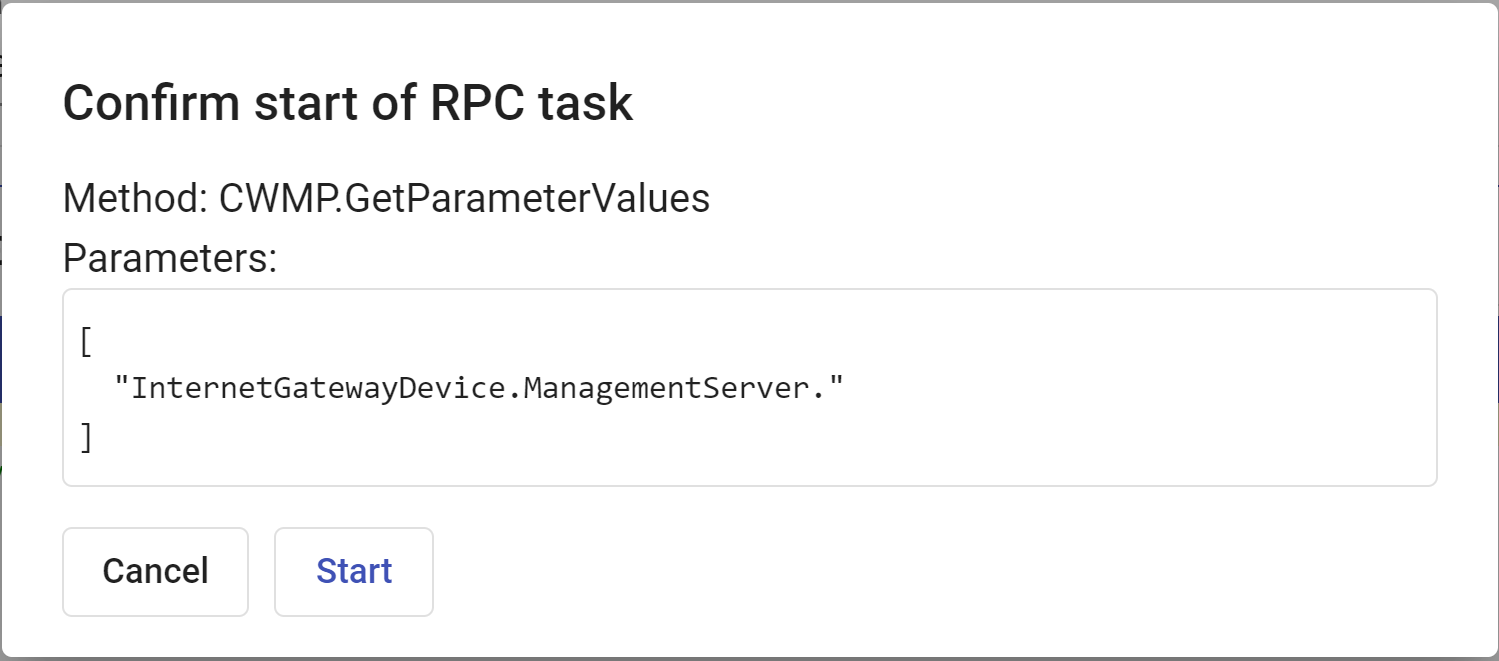
A special message will notify you about execution of the task.

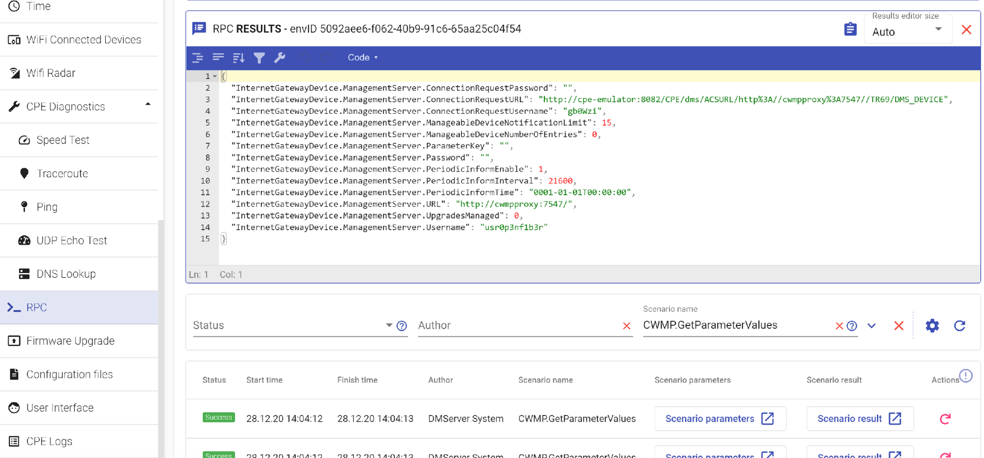
The results of the executed RPC task will appear in a special window in the center of the page. Below you will see the table with tracking of execution statistics of such RPC, with indication of start and end time of execution, execution status, author, scenario parameters and results. If you want to restart the previously executed RPC method just click on the Actions icon ![]() on the opposite side of such a scenario.
on the opposite side of such a scenario.
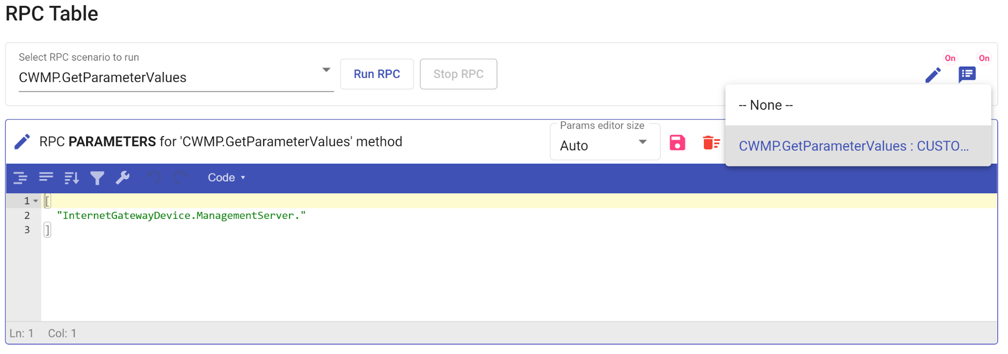
If you need to make any changes to RPC parameters, you can activate RPC parameters editor ![]() .
.
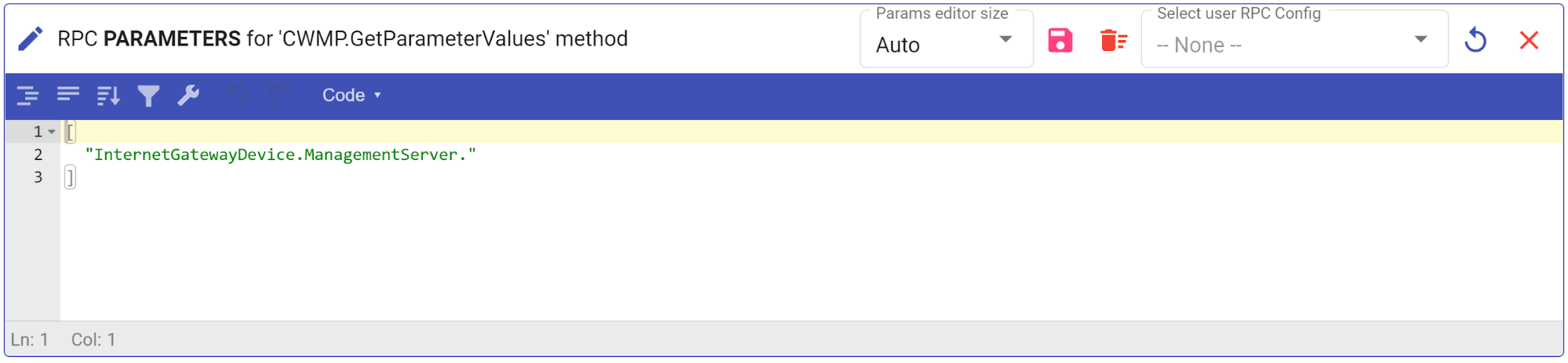
Enter the required custom parameters in the window that opens above the results of the previously executed RPC scenario , then click on the ![]() icon.
icon.

Add additional configurations to the RPC scenario by filling in the required fields then press the "Confirm" button to save all changes that you previously made. You will see the notification that your changes were applied.

The custom configuration with additional parameters will then be displayed in the Select user RPC configuration window.
Select it and press "Run RPC" button again to start task execution. After executing an RPC all received results of the custom RPC scenario will be displayed in the corresponding Results window. Other RPC scenarios can also be called in the same way.
To delete custom parameters, click on ![]() icon. If you want to hide the window with the results of the last executed RPC method and leave only chronological tracking of execution statistics, turn the RPC result editor off by moving the switch to the corresponding position
icon. If you want to hide the window with the results of the last executed RPC method and leave only chronological tracking of execution statistics, turn the RPC result editor off by moving the switch to the corresponding position ![]() .
.
Firmware upgrade
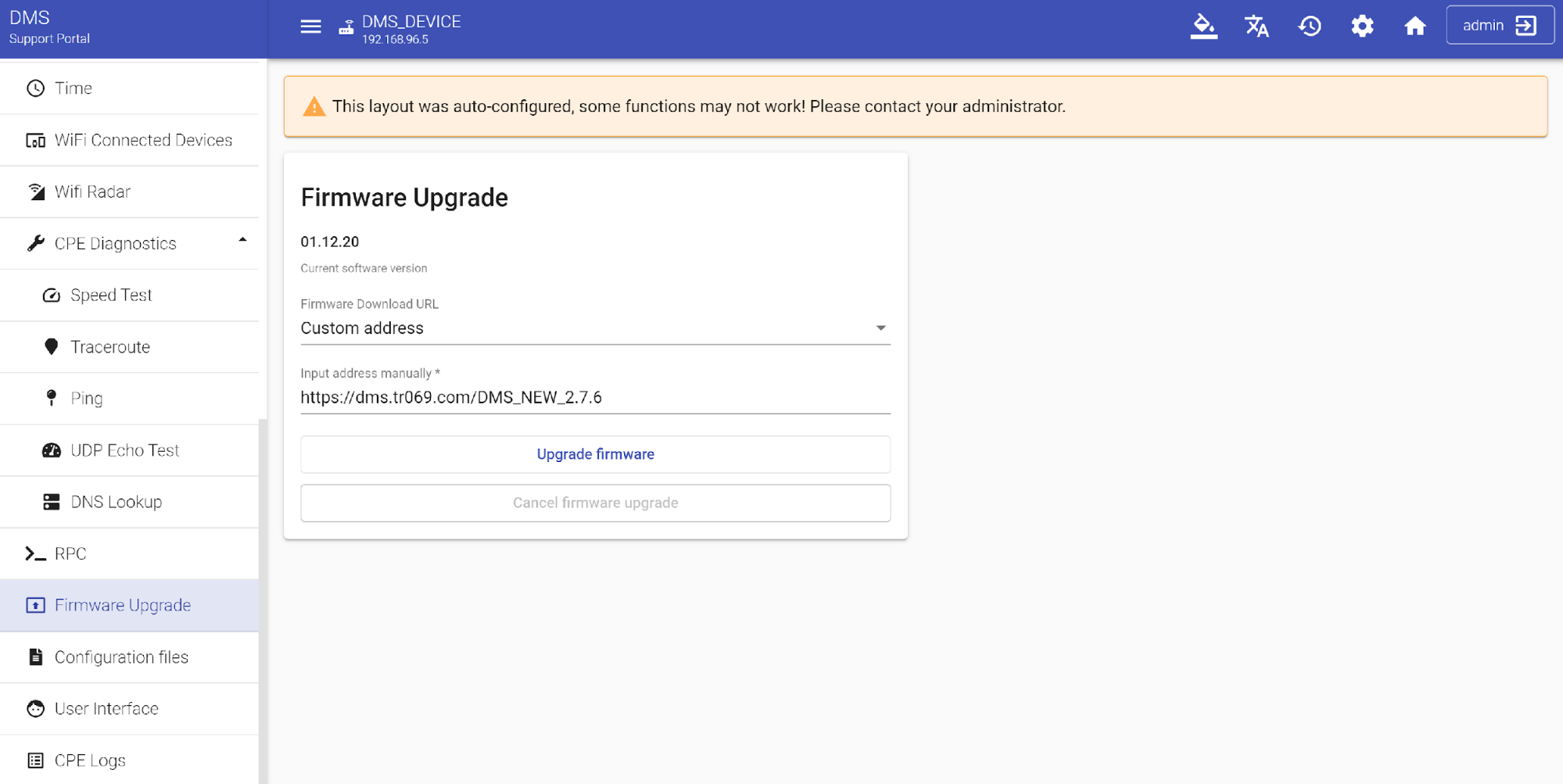
Firmware upgrades allow you to take advantage of the latest features and security enhancements on your CPE device. It also allows you to quickly and easily manage firmware versions on any of your devices. To check the latest firmware version and upgrade the active firmware press "Firmware Upgrade" button on the left side menu. The table with information about the installed current firmware version will be displayed on the screen , as well as other versions available for this CPE device.
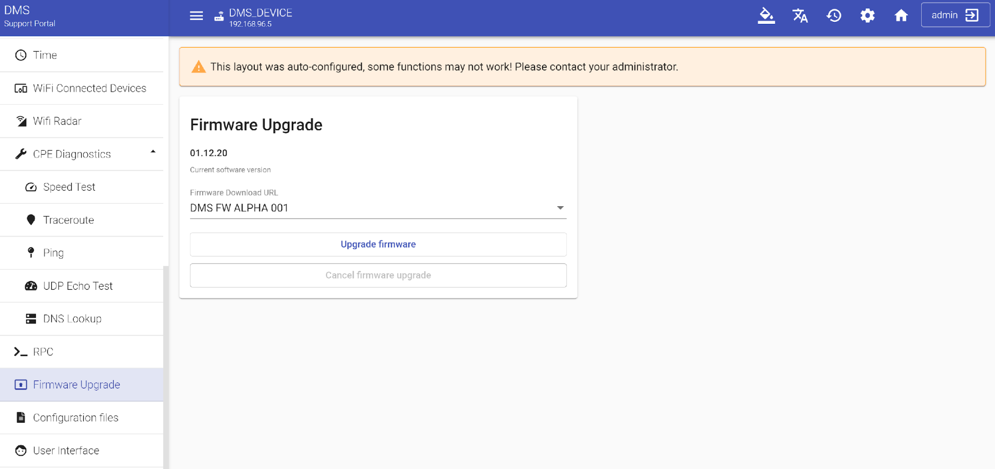
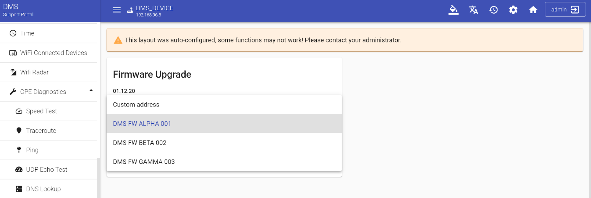
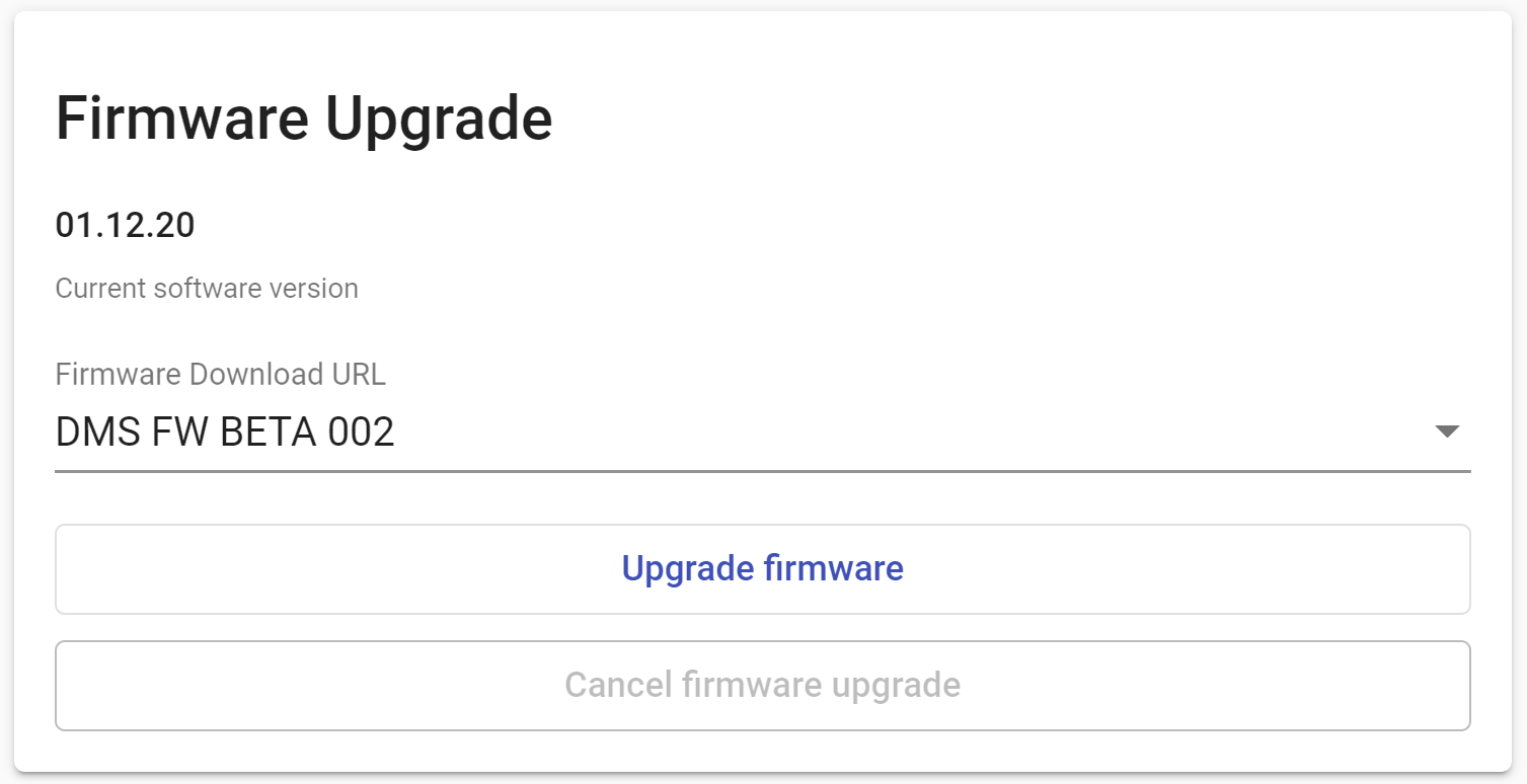
In order to begin upgrade process, select the required version from the dropdown list of available default URL variants.
then press "Upgrade firmware" button.
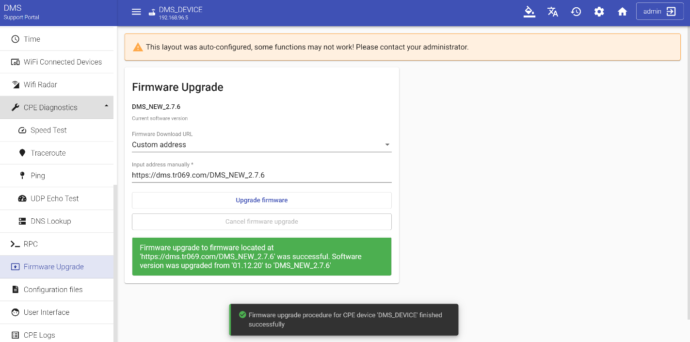
If for any reason you can’t find the required version, or you need to run the custom or experimental version of firmware that cannot be included in the list of available versions right now, you can specify the URL of your custom version which will be downloaded to the device from this location. To do this select the "Custom address" string in the dropdown menu then input your address and press "Upgrade firmware" button.
Wait for confirmation that the firmware upgrade procedure for CPE device was successfully finished.
Configuration files
Configuration file is a binary or text file used to store settings of computer programs, and thus determines the behavior of any application, computer or network device.
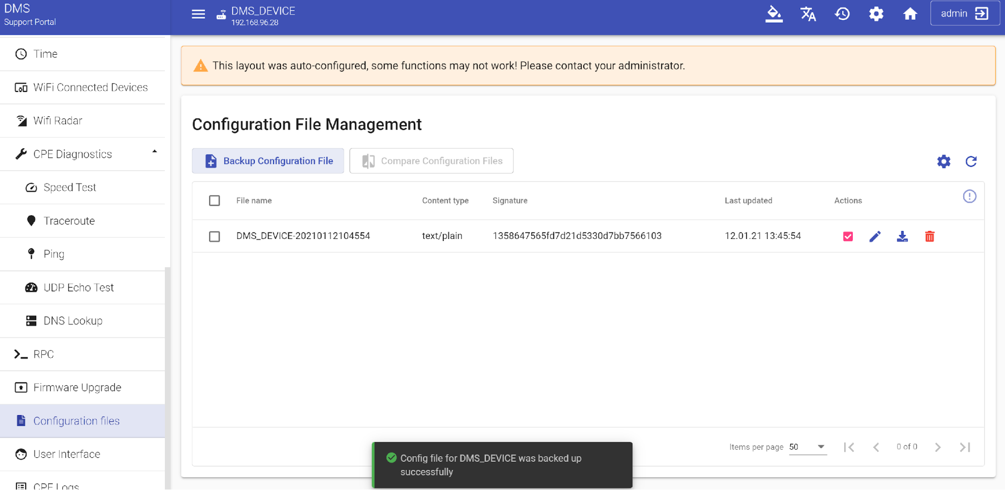
When you select "Configuration files" section in the left-side menu, you see a table with such partitions as "File name", which includes the device name and file creation timestamp, "Content type" that indicates the file type (text or binary), "Signature" - the internal file identifier in the file manager, "Last update" - the time when the file was last modified and "Actions" - the actions that can be applied to this file.
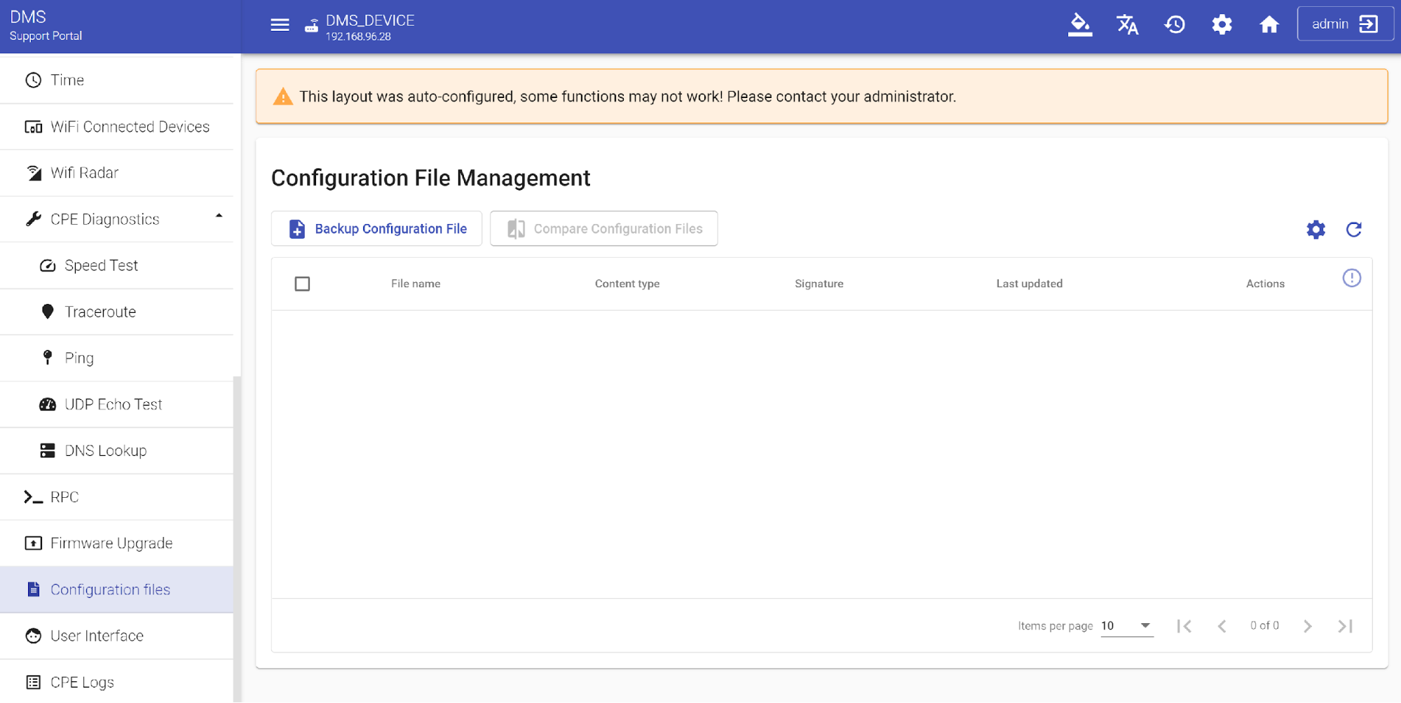
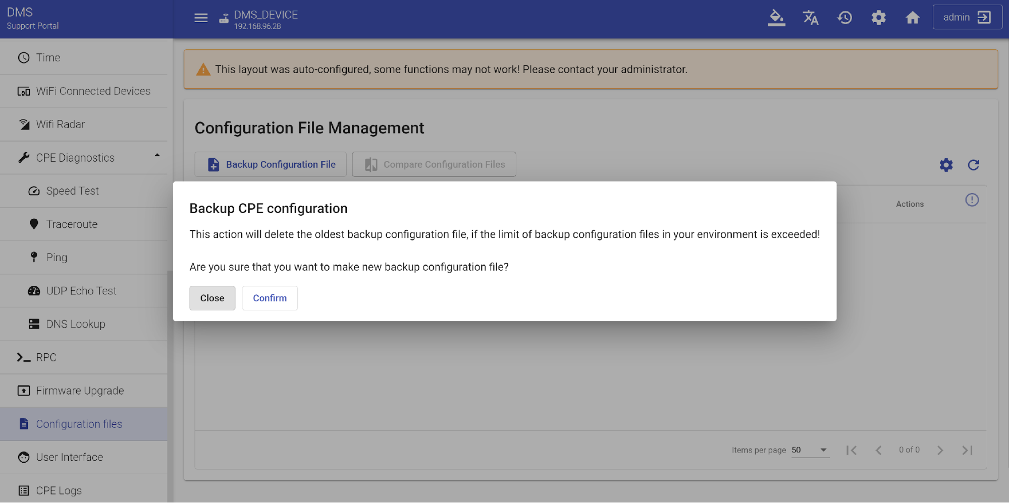
Press the "Backup Configuration file" button to create a configuration file for this device and confirm the action by clicking "Confirm" button.
Wait for the confirmation message that the configuration file has been successfully created. By default, the table displays up to 5 last created configuration files. A table view controller ![]() lets you configure the layout and content of an entire table. The procedure is similar to the one that we described above.
lets you configure the layout and content of an entire table. The procedure is similar to the one that we described above.
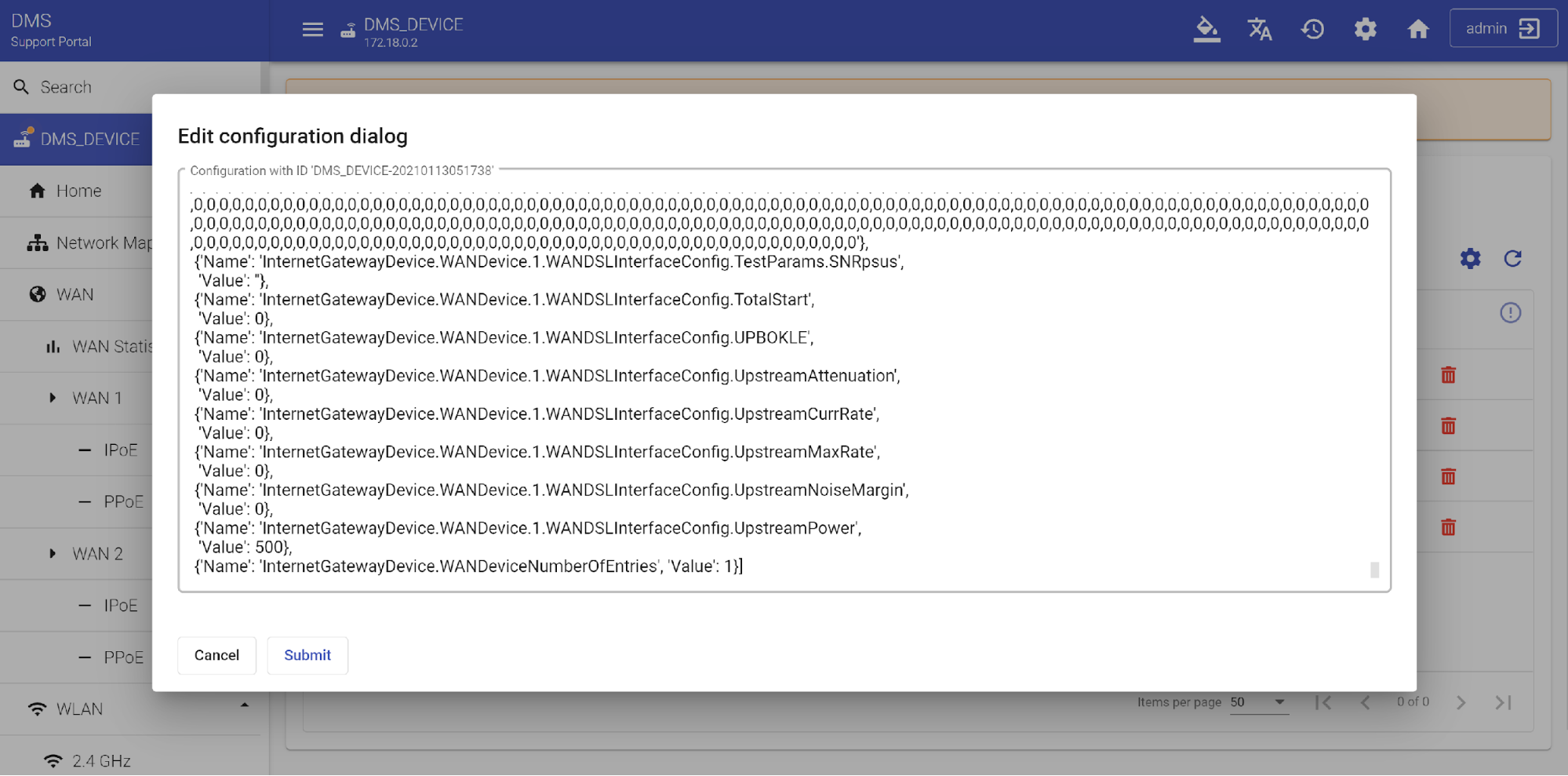
You can download the original config file to your PC ![]() . Edit it
. Edit it ![]() by making the necessary changes to the structure and pressing the "Submit" button.
by making the necessary changes to the structure and pressing the "Submit" button.
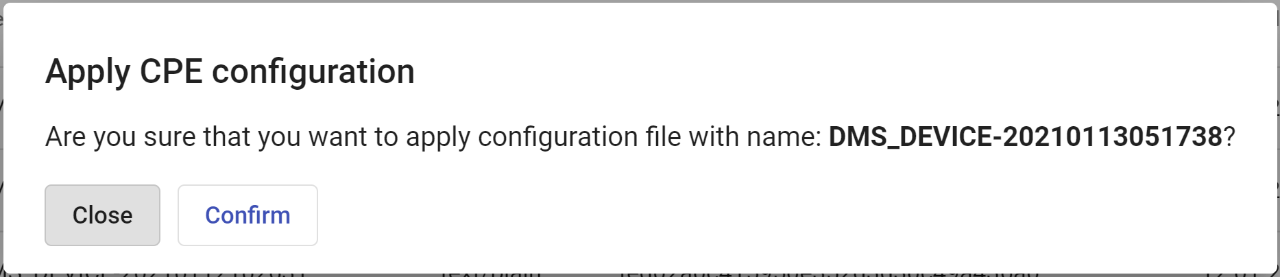
When necessary, you can apply this file to your CPE device ![]() .
.
and delete it if you don’t need it anymore ![]() .
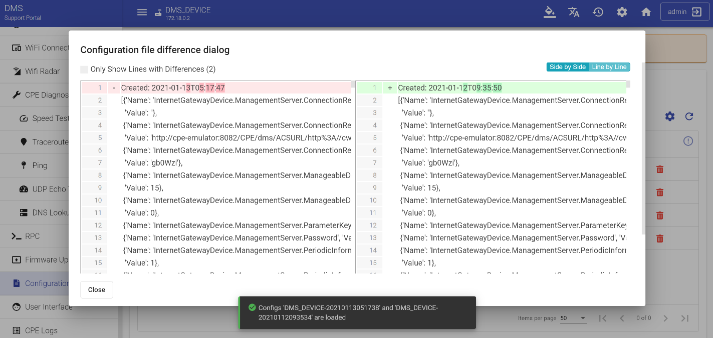
Also, you can compare several configuration files if you need to find the existing differences or correct the previously made changes.
.
Also, you can compare several configuration files if you need to find the existing differences or correct the previously made changes.
User Settings
The "User Settings" section allows managing user configurations. It includes the "Users Table" and "User Interface" windows.
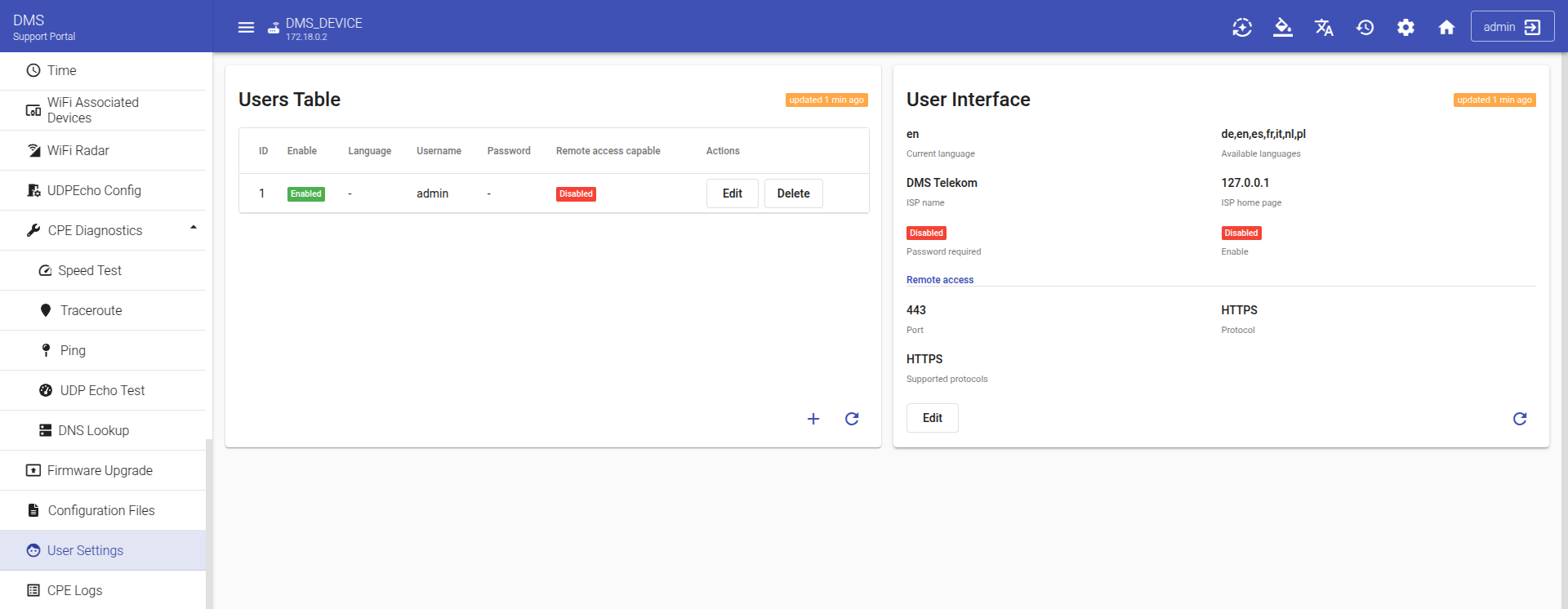
The "Users Table" window is designed for managing users on the CPE device. To add a new user, click ![]() button.
button.
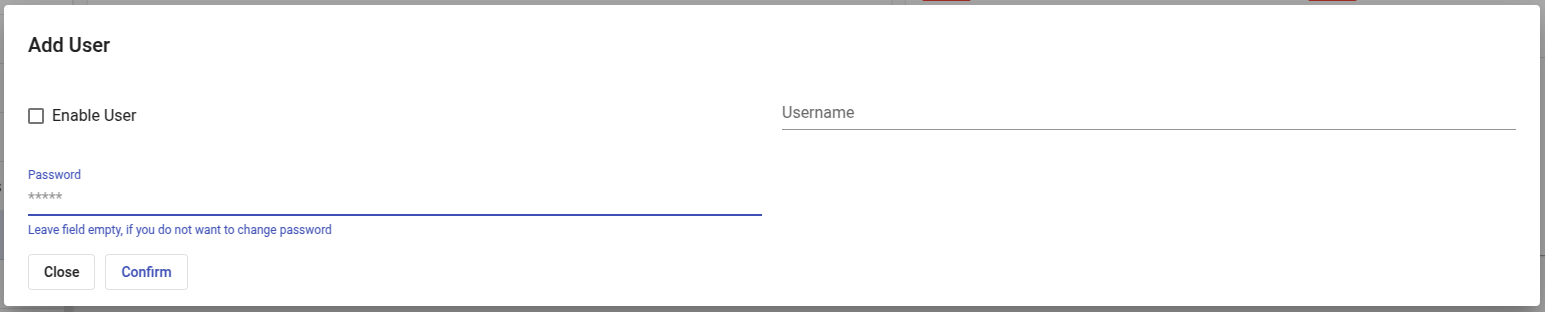
Enter a username and password for the new user, then click "Confirm" to save. To edit a user, click "Edit"; to delete a user, click "Delete".
The "User Interface" window is designed to manage the device's user interface settings. It includes key parameters such as interface language, ISP name, as well as security settings and connection protocol.
To set the language, click the "Edit" button and select a language from the available options (de, en, es, fr, it, nl, pl). Other fields in the pop-up window are also editable.
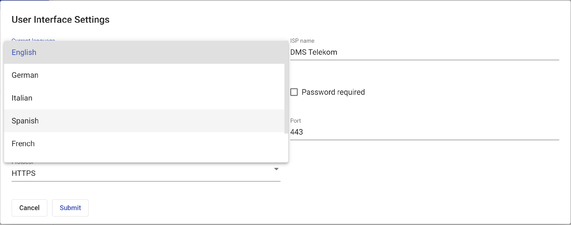
They contain information about the Internet Service Provider ("ISP name") and its network address. Destination TCP port required for remote access connection and type of used protocol.
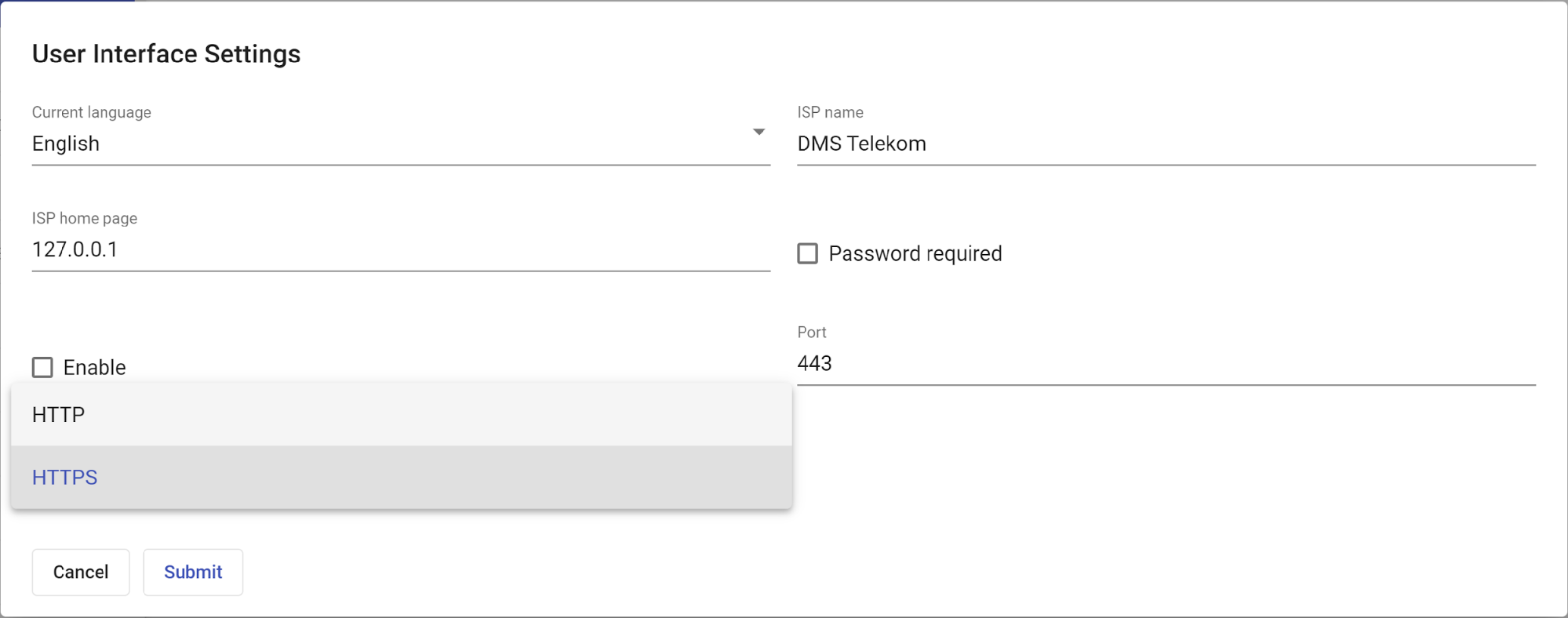
Choose the required values and set password if necessary, then press "Submit" button to apply all settings.
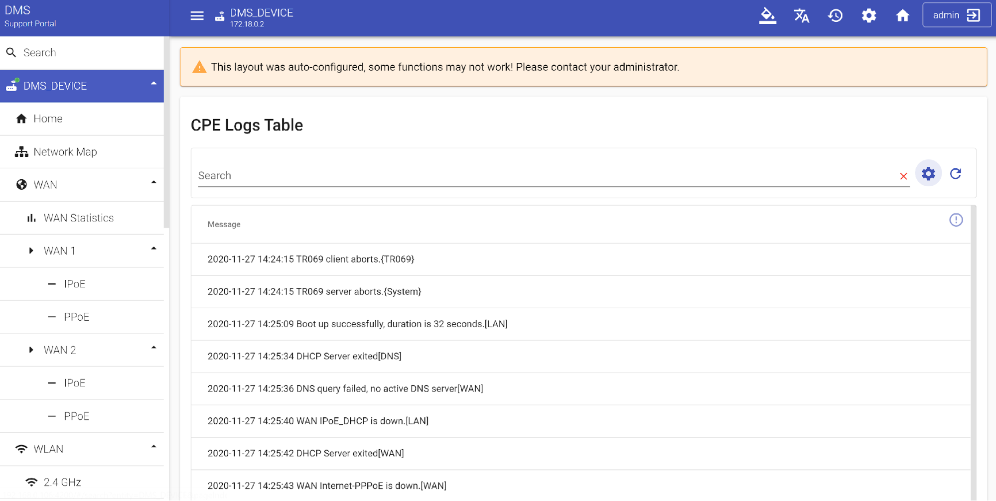
CPE Logs
You can use this section for searching specific records in a log file received from a device. The search can be carried out either by the full text of the log or by its substring. The columns displayed in the table depend on the logging structure on the device. In the absence of any data or inability to recognize it, it will not be displayed in the table
WiFi Associated Devices
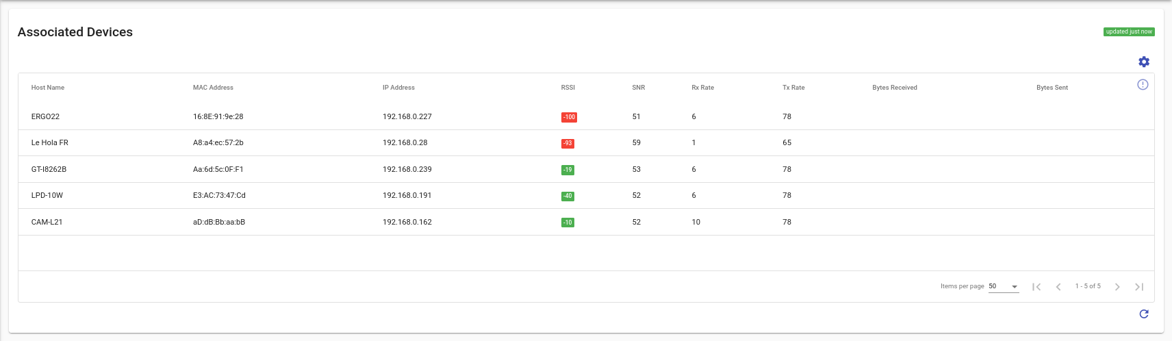
The Associated Devices panel displays a list of devices connected to the Wi-Fi network along with their main attributes, such as host name, MAC address, IP address, signal strength, and data transmission parameters. It allows users to quickly view and monitor the status of each device, updating information in real-time.
WiFi Radar
The WI-FI Radar table of the Support Portal displays the selected CPE device and also other nearby devices in the spectrum. The table shows the possible frequency range occupied by the selected device (2.4 GHz or 5 GHz) and the quality of the channel it is on. The vertical axis of the table shows the received signal strength (RSSI) in dBm. Signal level measurement is often required for accurate diagnostic of problems that cause device interruption and network dropout.
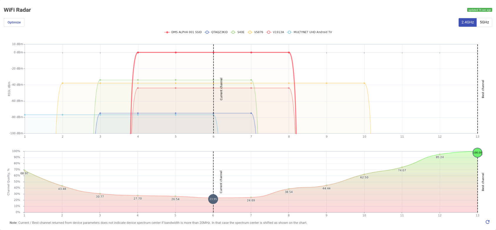
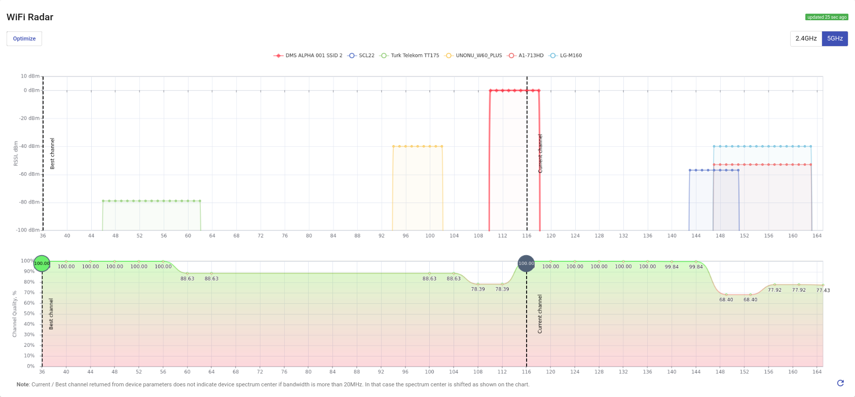
The table also displays the signal strength of neighboring devices that are affecting your device. You can remove one or more displayed neighboring devices from the chart when you need it. To return their visualization in the chart, click the "Reset graph" button. Besides that, the best and worst channels for the functioning of your device are displayed on the channel quality graph for that device.
If you want to optimize the operation of selected device in the manual mode, press the "Optimize" button.

In the appeared dialog window select the desired channel and confirm your decision by activating change channel variable. Then press "Submit" button to apply changes.
UDPEcho Config
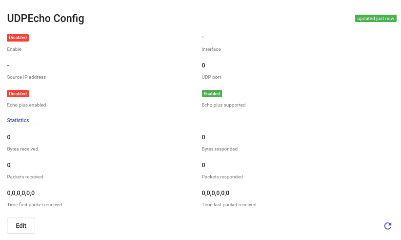
If UDP Echo monitoring is supported and available, this section will include the settings for the UDP Echo diagnostic server on the device, allowing to send a UDP Echo packet to the device and evaluate network performance based on its response.
CPE Diagnostics
CPE device diagnostics is a mandatory and regular procedure that focused on checking the correct operation of the appliance and assessing its technical condition. Diagnostics are required for several reasons. The main ones are verification the condition of equipment and its technical characteristics (indicators) and assessment the quality of supplied devices (defects, lower device health indicators than those mentioned in specification for this device, etc.).
There are 5 diagnostic tests available to run for your CPE: Speed test (Upload/Download), Traceroute, Ping, UDP Echo, DNS Lookup. Each test triggers respective RPC and is shown in Scenario History in RPC widget.
Here are their detailed descriptions:
Speed test
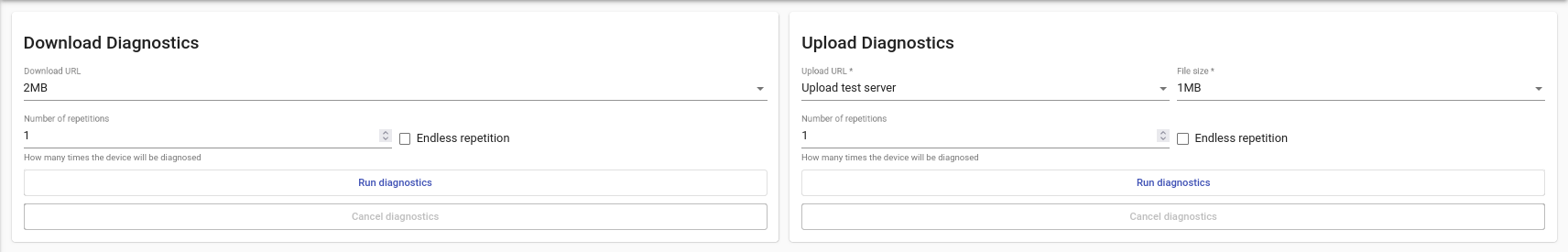
The speed test includes the Upload and Download Speed tests. The Upload and Download Speed tests provide insight into the network bandwidth between the CPE and the test server hosting the FTP or HTTP upload/download files service and measure the bandwidth speed.
You can specify download/upload URL, upload file size and number of repetitions up to endless repetition.
If successful it returns exact download or upload speeds in Mbps.

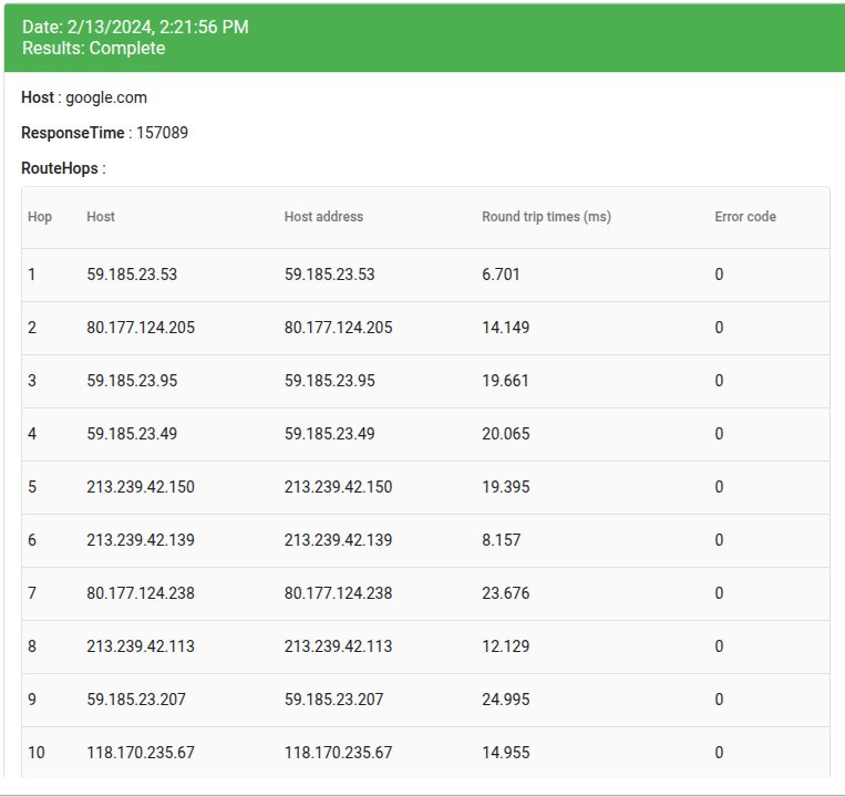
Traceroute
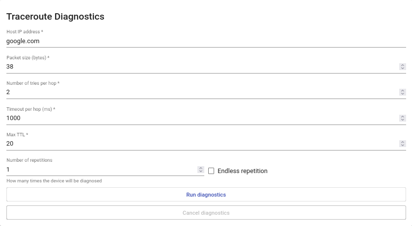
It is essentially a convenient device and network diagnostic tool. It helps to determine if the packet has been sent from the device and what path your data takes to reach a goal without actually sending the data. Unlike Ping, which is a quick tool to determine the possibility to reach a specific device or server and to identify the time it takes to send and receive packet back, the Traceroute finds the exact route to the device and the time taken for each step (hop).
You can specify host IP address, packet size, number of tries per hop, timeout per hop (ms), max TTL (how many times the device will be diagnosed) and number of repetitions up to endless repetition.
If successful it returns a table of IP addresses and trip times.
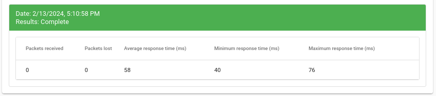
Ping
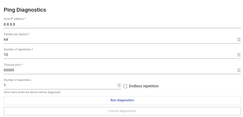
Ping is a diagnostic tool that tests the connection between two devices or hosts on a network. The Ping function of our server checks whether a data packet can be transmitted to an address without errors. It also determines if a certain IP address is available on the network and is used to determine and verify that the host device the user is trying to reach is actually working. Ping is mainly used to diagnose Internet connections.
You can specify host IP address, packet size, timeout in ms and number of repetitions up to endless repetition.
If successful it returns minimum, maximum and average response time.
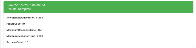
UDP Echo Test
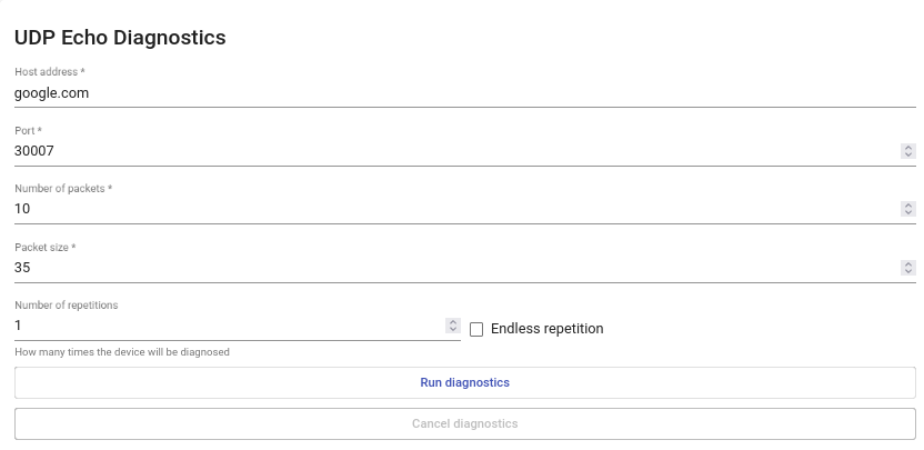
UDP Echo test gives insight into different factors affecting service quality, such as packet loss and overall network path quality.
You can specify host address, port number, number of packets, packet size and number of repetitions up to endless repetition.
If successful it returns a set of parameters: AverageResponseTime, FailureCount, MaximumResponseTime, MinimumResponseTime, SuccessCount.
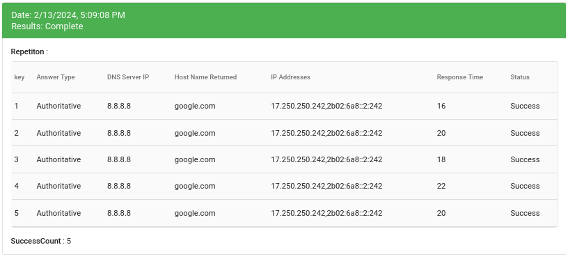
DNS Lookup
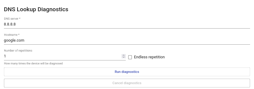
DNS lookup performs simple forward and reverse DNS queries to get information about the IP address or hostname and to test the DNS servers used by the firewall.
You can specify DNS Server IP, Hostname and number of repetitions up to endless repetition.
If successful it returns a table of DNS Server IPs, Host Names, IP Addresses and Response Times.
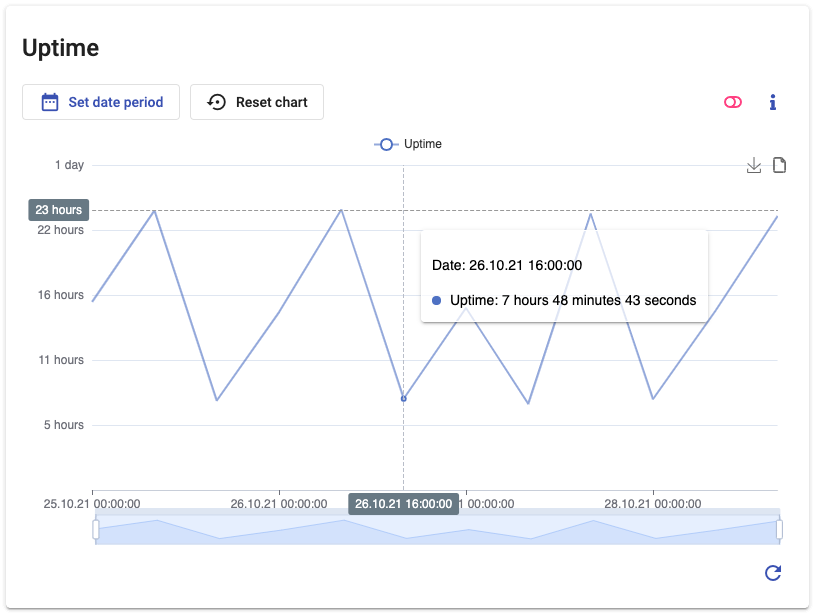
KPI Widget
If KPI collection module (Service Quality Management, SQM) is installed alongside DMS package the Support Portal can also show various metrics-related historical graphics via KPI widgets. It should be noted, that CPEs Data Models also need to provide parameters that SQM can collect.
Graphics provided through KPI widget can be used by tech support employees for such thing as:
- responding quickly to errors and malfunctions;
- detecting different patterns and trends;
- looking for "weak spots" in networks and customer experience;
- being more efficient with operational costs, time and other resources;
More on that in introduction to SQM API.
Here's a list of tabs that can possibly be generated inside the widget:
Common
- Uptime
- Memory
- Process
Local Network
- Associated Devices RSSI
- Network Map
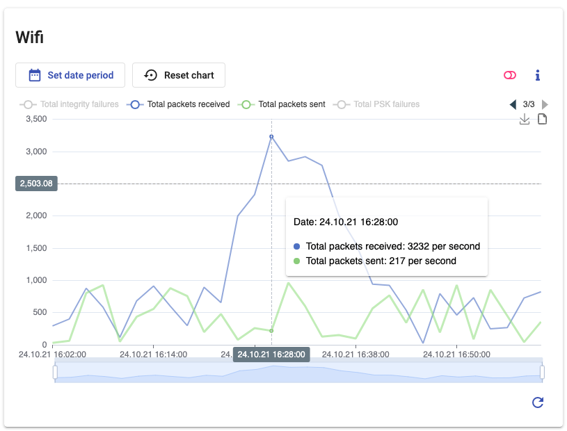
Wi-Fi
- Wifi (broadcast/discard/multicast/total packets)
- Wifi Channel
- Wifi Bytes
Ethernet (LAN, WAN)
- bytes
- packets
Voice
- Voice (incoming/outgoing call received/connected/answered)
Diagnostics
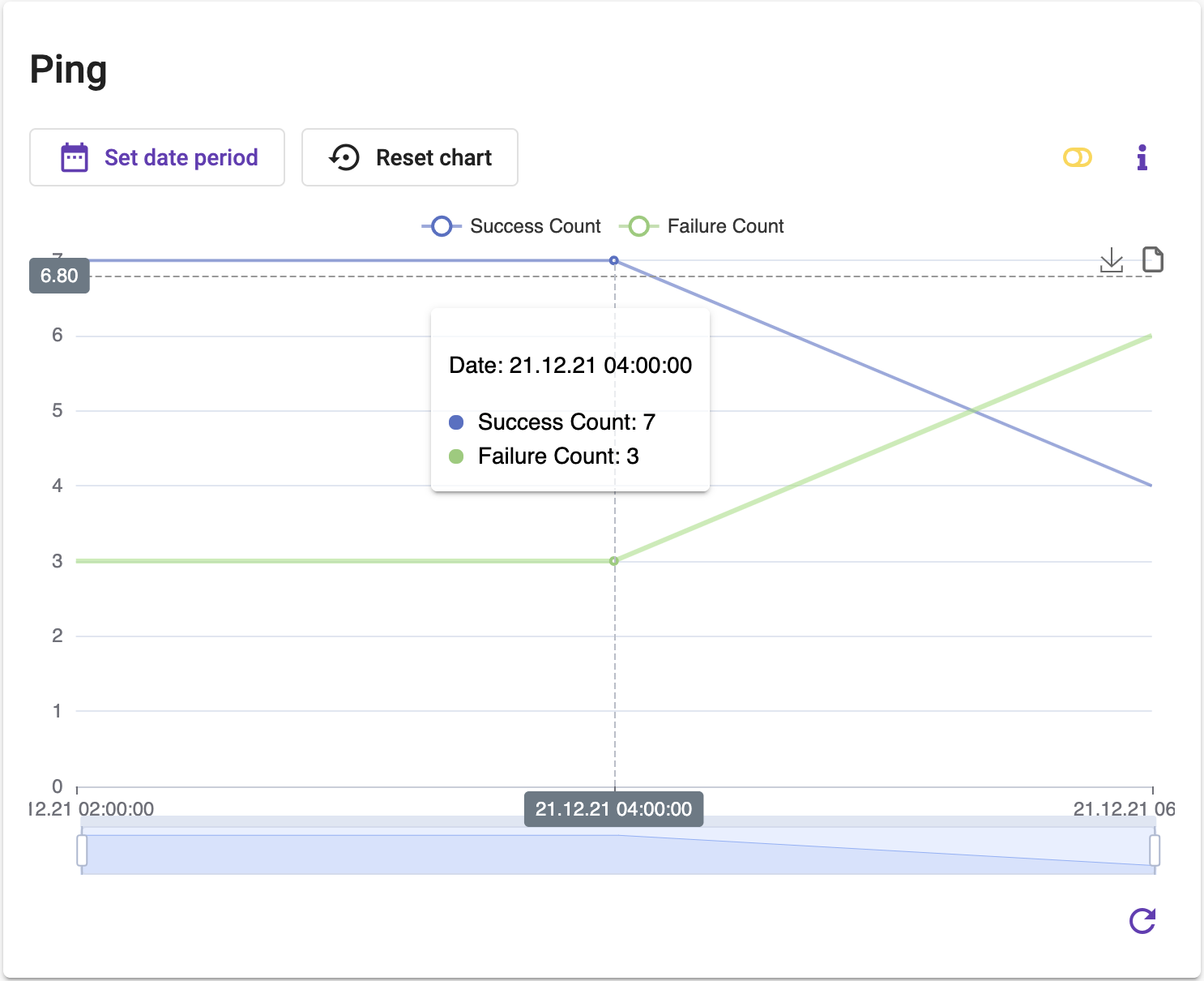
- Ping (success/failure, response time)
Some are illustration of some specific device statistics:
Common - Uptime
Wi-Fi
Diagnostics - Ping
Local Network - Associated Devices RSSI

Local Network - Network Map